Way that competition in square wave at 200 kHz?? This is an audio amp and no one showed in any blind listening test(all here are just subjective opinions or selling advertisements) that so high RS(over some needed level) gives better sound. For someone a higher distortion amp could sound better at heights and that could be just result of high distortion harmonics.
Damir, as I mentioned in the other thread, I hate dealing with 1MHz-ish bandwidth, etc.
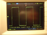
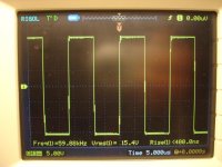
But what I really like - 360nS rise/fall time and -2.6 degrees phase shift @ 20kHz. Those two parameters make it sound better. Following the complex input signal more accurately.
I just did not find the other way of reaching this level of accuracy with the narrower bandwidth... so far 😉
Damir, as I mentioned in the other thread, I hate dealing with 1MHz-ish bandwidth, etc.
But what I really like - 360nS rise/fall time and -2.6 degrees phase shift @ 20kHz. Those two parameters make it sound better. Following the complex input signal more accurately.
I just did not find the other way of reaching this level of accuracy with the narrower bandwidth... so far 😉
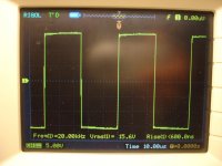
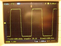
It's OK to have high SR as a result of a topology used, but if a very high SR became the goal in an audio amp, and to show how much better my 200 kHz square wave looks then yours then that is strange for me.
Damir, as I mentioned in the other thread, I hate dealing with 1MHz-ish bandwidth, etc.
But what I really like - 360nS rise/fall time and -2.6 degrees phase shift @ 20kHz. Those two parameters make it sound better. Following the complex input signal more accurately.
I just did not find the other way of reaching this level of accuracy with the narrower bandwidth... so far 😉
If it affect sound we would like you to describe your experience if possible. There are good amplifiers with no Mhz bandwidth. What is achieved by extending to RF?
hehe trimm caps, something very familiar to me
Oh, just a moment Lazy Cat, trim capacitors (for this board)is my invention.

It's on my plan to do the same for drivers(out) compensation.
Can you give more details for trimming process?
At what frequency and output level you scope, when trimming these?
Thimios.
Attachments
Last edited:
Μy god the same trimmers on a nice smd board!😱Thimios, I trimm-caps the amps for years. My method is very repetative and the result is compensation's sweet spot, nothing special indeed, but ensures the amp will give its max performance within certain schematics.
Last edited:
If it affect sound we would like you to describe your experience if possible. There are good amplifiers with no Mhz bandwidth. What is achieved by extending to RF?
Fully agree, there are excellent amplifiers with no MHz bandwidth and I've got some of them 🙂
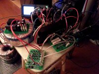
OK, a few words about the setup I use for sound testing.
Sources are all digital - SACD/DVDA/BD player and media player allowing to play high resolution recordings (up to 24/192), including multi-channel ones - both used as a "transport" for appropriate source material.
Digital processor - Onkyo receiver with high-enough quality multi-channel DAC, used for D/A conversion and volume control. I take the signal from its line outputs. Speakers - all of them are Monitor Audio - RS8 as fronts (also used in stereo mode), 2 RS1s as surround and RS-Centre for multi-channel setup.
Now - what sits between the line-outs and the speakers.
Audiolab 8000x7 - my main "working horse", like it a lot, use it one way or the other for all multi-channel listening.
My PowerAmp-Pio prototype, designed taking Pioneer M3 Exclusive as a basis - classical VFA - 2 LTPs, current mirror, EF3. Excellent sound, very "controlled", highly detailed - most of experienced listeners like it a lot.
I often use it as a reference, comparing other prototypes' sound with it.
OK, finally - CFA. This is my first design in this area with the purpose to see CFA principles really bring some significant benefits.
I've got 2 options of the input buffer:
1-st one is my own design, based on OTA (Operational Transconductance Amplifier) topology (lots of current mirrors). Great performance in balanced mode.
2-nd one is the diamond input and current-conveyor based line amp, designed by Damir (dadod). This one shows even better performance in non-balanced mode, than the 1-st one, so at the moment I use this one in the prototype.
Then goes trans-impedance stage and power section with very light compensation, allowing wide bandwidth and high overall speed.
After initial testing, measurements, compensation fine-tuning, I've spent couple of days auditioning it with different sorts of music.
First impression - remarkably natural sound. Highest clarity in all the audio bandwidth, especially noticeable on acoustic instruments - piano, violins, horns, drums. Drums and all sorts of percussion sound perfectly! Well-recorded jazz trios/quartets, ethnic music as well as early Pink Floyd, Livin' Blues, acoustic Eagles concert (Hell freezes over) sound especially good with highest clarity, dynamic and gentle power at the same time.
I think, technically, the main reasons for this are the following:
- Low overall harmonic distortion - ok, nothing special, there are lots of highly linear amplifiers. However, in this design it is almost frequency-independent, which is always a plus;
- Very small and almost frequency-independent phase shift. At 20kHz it reaches only -2.6 degrees;
- Very high slew rate, allowing accurate following the input signal regardless how fast the rises or falls are. Perfect square or any other complex signal handling.
Last two benefits are rather typical for CFA topology. When I say frequency-independent, I mean low dependency within the audio bandwidth (let say, 20Hz - 20kHz).
MHz bandwidth is actually a downside of all this beauty. It requires very careful and accurate compensation, a lot of attention to wiring, etc.
So, I consider this "experiment" as successful one and plan to explore it further in the direction of simplification and ease of build, preserving all the benefits.
And this first prototype will be installed in a nice Italian compartment and used as one more reference, though I still like my "classic" Pio a lot 🙂
If you have more questions - just let me know, I can listen, measure, test something, etc.
Sorry for a long story - hope it will be useful 😛
Cheers,
Valery
Attachments
Thimios, I trimm-caps the amps for years. My method is very repetative and the result is compensation's sweet spot, nothing special indeed, but ensures the amp will give its max performance within certain schematics.
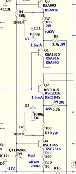
Actually, I find trim-caps very useful for CFA designs, where the optimal compensation value may be somewhere between 1.5 and 3.5 pF, though I never used them before. Maybe next time 😉
Thank you very much, it is really report. That motivate me to look for high sr low hd design. Well, maybe try some cf, if vf attempts fail.
Yes, it will be interesting to compare measurements other than 200kHz square.
Yes, it will be interesting to compare measurements other than 200kHz square.
OK, finally - CFA. This is my first design in this area with the purpose to see CFA principles really bring some significant benefits.
I've got 2 options of the input buffer:
Then goes trans-impedance stage and power section with very light compensation, allowing wide bandwidth and high overall speed.
First impression - remarkably natural sound. Highest clarity in all the audio bandwidth, especially noticeable on acoustic instruments - piano, violins, horns, drums. Drums and all sorts of percussion sound perfectly! Well-recorded jazz trios/quartets, ethnic music as well as early Pink Floyd, Livin' Blues, acoustic Eagles concert (Hell freezes over) sound especially good with highest clarity, dynamic and gentle power at the same time.
So, I consider this "experiment" as successful one and plan to explore it further in the direction of simplification and ease of build, preserving all the benefits.
Cheers,
Valery
😎🙂 +1
Last edited:
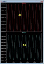
Hi OS ,is it necessary to put these capacitors NP type?
Looks like the "Cat" is using polarized. 😀
Use either .... (below 1) C5 / C6 - they only "see" positive and negative.
(below 2) is the polarity marked caps in the circuit and how you
(could) protect them from any unexpected reverse polarity condition.
10-16V 1Kuf NP's are common here in the states.
Your call !!
PS - with the diodes ... still only 17ppm 1/2 power/4R THD20K .
OS
Attachments
Last edited:
Also ... all this trimmin' 😀 Geeeezzz !
Just get bold and drop some 22-27pF SM comp. caps in there !!
Lower the resistance of the CFB network - this amp is quite
resistant to oscillation.
22pf (C9-10)+ 1.5K/47R (R7/8 -9/10) = 450V/us + SR .....
with just a slight "ring" 😱 .
OS
Just get bold and drop some 22-27pF SM comp. caps in there !!
Lower the resistance of the CFB network - this amp is quite
resistant to oscillation.
22pf (C9-10)+ 1.5K/47R (R7/8 -9/10) = 450V/us + SR .....
with just a slight "ring" 😱 .
OS
Thaks OS,my last test is,R8,R9=1KAlso ... all this trimmin' 😀 Geeeezzz !
Just get bold and drop some 22-27pF SM comp. caps in there !!
Lower the resistance of the CFB network - this amp is quite
resistant to oscillation.
22pf (C9-10)+ 1.5K/47R (R7/8 -9/10) = 450V/us + SR .....
with just a slight "ring" 😱 .
OS
R7,R10=33R
Probably you say R8,R9=1K5
R7,R10=47R?

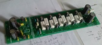
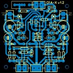
Beautiful board Anistardy but way used these big resistors?Second built...
Waiting for components....
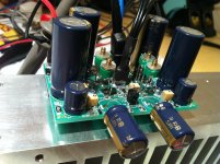
Here my second Inp CFA-X V1.2
This soldered with lead free solder
Attachments
Last edited:
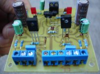
A question I have based on the pictures that Thimios has posted. Why do some people leave the leads on some devices like the transistors so long with the devices sitting so prominently high off the board surface? I would think for the same reason that we would want the traces on a board as short as possible we would want the same with the installed components, am I wrong in this assumption or is it just for ease of disassembly that I am seeing this or quick modifications?
A question I have based on the pictures that Thimios has posted. Why do some people leave the leads on some devices like the transistors so long with the devices sitting so prominently high off the board surface? I would think for the same reason that we would want the traces on a board as short as possible we would want the same with the installed components, am I wrong in this assumption or is it just for ease of disassembly that I am seeing this or quick modifications?
These A1381,C3503 trans.are difficult to find in Greece(thanks SONYA for these pairs) so i didn't cut not stress these at least up to final version.
- Home
- Amplifiers
- Solid State
- Slewmaster - CFA vs. VFA "Rumble"