sorry for above. i reviewed, the optimum combo must be slow-fast-slow devices.
slow-fast-fast is also okay. 🙂
hope it helps.
slow-fast-fast is also okay. 🙂
hope it helps.
one thing to note also is the size of the driver used for 2 pairs versus the 3 or 5 pairs board. the former uses to-220 while the latter use to-264 which is the same size as the output transistors. 🙂
Jason has built one, I will ask him to help me.
thanks, Terry
great!
My plan for VAS is MJE340/350, Drivers MJL3281/1302 and OP MJL4281/4302. That's what I have on hand. Looking for watt rating on resistors and voltages for caps.
Thanks, Terry
Thanks, Terry
Some kind guy maybe able to help you but the harder parts to determine are the pre-driver, driver, output combo. If i remember right these should be fast- slow-faster devices.
I use faster (ft = 200Mhz) - fast (ft = 100 MHz) - slow (ft = 30 Mhz) 😎
Care anyone to explain to us (learners) the significance of Ft speed in relation to the next device in the signal path, considering audio signals can not reach this frequency level and its corresponding harmonics?
Care anyone to explain to us (learners) the significance of Ft speed in relation to the next device in the signal path, considering audio signals can not reach this frequency level and its corresponding harmonics?
I don't understand your question.
fT is frequency where hFE of BJT is 1. Ideally, hFE don't change if frequency change. That's what we want 😀.
^sorry for the out of topic question. i just need a simple answer like how does it affect the operation stability of an amplifier, or sound quality if the pre-driver, driver, output transistor configuration does not follow an Ft order like the one mentioned above considering audio signals and its harmonics are far too low from the lowest Ft specs (30 MHz) among the given transistors?
Bimo.
I thought that the last device would be the fastest and the first the slowest.
No, I have different compensation than OS design. And my amp is stable 😎
Jaagut, as long as fT >> 20kHz, I think THD is not affected by fT.
Sim result show, high fT can give more slew rate in CFA topology.
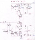
Here is the modified CFA-X V1.2 but be careful ,my power supply is +/-50V!Hi thimios, can you show us the schematic of your cfa-x with complete modifed values of compensation caps and feedback resistors? I am going to iterate this build soon. My build is posted in our local forum.
SLEWMASTER Build
Attachments
^sorry for the out of topic question. i just need a simple answer like how does it affect the operation stability of an amplifier, or sound quality if the pre-driver, driver, output transistor configuration does not follow an Ft order like the one mentioned above considering audio signals and its harmonics are far too low from the lowest Ft specs (30 MHz) among the given transistors?
there is no simple answer, why do you think Japanese amps used semicons with high fT's and hFE's that doesn't droop too much with current?
you can run simulations and try using trannies that are low fT's and low hFE's and see what happpens....
The B-C leakage of the transistors will be dominant in the distortion of this circuit. It seems like a lot of extra transistors for not much gain when you consider this. It could be improved, but it would have a lot of transistors. It could be a more-transistors-less-resistors approach.
I would start with Dado's GainWire where I helped to lower the B-C leakage using Baxandall-cascoded current mirrors.
I'm wondering if this is usefull as IPS?Never did get an answer for that question
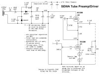
I have a 6N3P buffer that runs on 50V rails, so I'm sure a CFA could be made with a tube input. 180V rails could certainly be done, but with special requirements.
The B-C leakage of the transistors will be dominant in the distortion of this circuit. It seems like a lot of extra transistors for not much gain when you consider this. It could be improved, but it would have a lot of transistors. It could be a more-transistors-less-resistors approach.
I would start with Dado's GainWire where I helped to lower the B-C leakage using Baxandall-cascoded current mirrors.
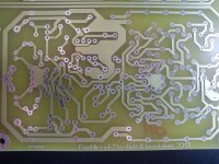
And this is the PCB, look here.
Attachments
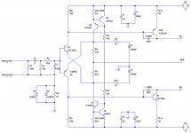
This should be the VSSA front end based on Jason's boards. Take a look and see if everything looks correct.
Thanks, Terry
Thanks, Terry
Attachments
Last edited:
- Home
- Amplifiers
- Solid State
- Slewmaster - CFA vs. VFA "Rumble"