I suggested before that you may need the optional CSA / CSB components installed, have you tried that yet? Just put some 68pF on those pads, heck even 100pF if that is all you have handy. If there is an oscillation that may tame it.
OK I added the 82pf to csa/csb. The bias is not jumping but the heatsinks still can't keep up. Just too hot for my liking. I also changed R113 to 68R. That dropped the current to 15mA across R113 but the heatsink on the drivers it too hot to hold onto. I hooked up my scope but don't see anything unusual. There is still something amiss because when I payed music through it, after about 5 minutes the bias raised to about 70mV across the emitters. stopping the music brought it down to about 60mV but it just sat there. Then I unplugged the input and it dropped very quickly to the original setting.
Thanks, Terry
Thanks, Terry
What exactly are your pre/driver/OP devices ?
And , what exactly is the "jury rigged" CFA IPS you are using ?
(schema) ?
With these facts , (I'll put the "thinkin' cap on).
These things should not be happinin' 😀 !!
"heatsink on the drivers it too hot to hold onto" .... definitely something amiss here (oscillation)
drivers at idle should be COLD (they are huge - only 2-3W here).
OS
Last edited:
What exactly are your pre/driver/OP devices ?
Pre drivers - MJE340/350, drivers - MJW3281/MJW1302, outputs - MJL3282/MJL1302. All On Semi samples
And , what exactly is the "jury rigged" CFA IPS you are using ?
(schema) ?
Attached
With these facts , (I'll put the "thinkin' cap on).
These things should not be happinin' 😀 !!
"heatsink on the drivers it too hot to hold onto" .... definitely something amiss here (oscillation)
drivers at idle should be COLD (they are huge - only 2-3W here).
OS
Attachments

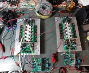
Hi Terry i see that your drivers out. are TO247 devices.
I have try this in the past but the result isn't good.
They oscillate badly so i returned to 2sa1837,2sc4793 .
PS. Just now i see that you haven't connect vas GND to STAR GROUND.
I have try this in the past but the result isn't good.
They oscillate badly so i returned to 2sa1837,2sc4793 .
PS. Just now i see that you haven't connect vas GND to STAR GROUND.
Attachments
Last edited:
It is an adaption of this.
http://www.diyaudio.com/forums/group-buys/251782-vssa-through-hole-version-jason.html
thimios
I can replace them with MJL3281/1302, MJL4381/4302, MJL21193/21194. I used the MJW because they were smaller.
Terry ,is this G2 point connected to Star Gnd?
You MUST connect these G2 points to star gnd!
You MUST connect these G2 points to star gnd!
Last edited:
Hi thimios,
No, I didn't realize it wasn't attached through the board. I will try that.
EDIT: I attached G2 to star. No change. The drivers are still too hot to hold in about 5 minutes.
I will try to mark up a schematic with voltages. It could be that I've got the IPS turned up to high.
Thanks, Terry
No, I didn't realize it wasn't attached through the board. I will try that.
EDIT: I attached G2 to star. No change. The drivers are still too hot to hold in about 5 minutes.
I will try to mark up a schematic with voltages. It could be that I've got the IPS turned up to high.
Thanks, Terry
Last edited:
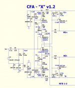
Never really looked at Jason's vssa (circuit).
(Below) are the changes i would make.
You would have to adjust VR1/3 to re- obtain
the standard 4.5-5ma "slewmaster" VAS current.
PS - you would then have a copy of the original "CFA-X"
OS
(Below) are the changes i would make.
You would have to adjust VR1/3 to re- obtain
the standard 4.5-5ma "slewmaster" VAS current.
PS - you would then have a copy of the original "CFA-X"
OS
Attachments
Last edited:
That's a shame, I posted it at least three times and asked for suggestions. The schematic you posted shows devices not being used. Adds a little confusion for me.
Hi Terry i see that your drivers out. are TO247 devices.
I have try this in the past but the result isn't good.
They oscillate badly so i returned to 2sa1837,2sc4793 .
PS. Just now i see that you haven't connect vas GND to STAR GROUND.
we must solve this !
Try lowering the driver base-stoppers to 2.2-4.7R (r111/112).
(or eliminate them - jumpers)
OS
That's a shame, I posted it at least three times and asked for suggestions. The schematic you posted shows devices not being used. Adds a little confusion for me.
We don't want no confusion. 😕
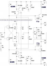
Raise the Re on the main VAS devices to 150R.
Bias those main VAS devices (bases) with 820 R (to rail).
Look at the "VSSA" that is meant to go with this OPS (below)
, as a reference.
I also noticed on jason's VSSA ... no zener regulation. You might
also be exceeding Vceo for many of the devices - CAREFUL !! 😱
You need mje340/350 - ksA/C devices that can handle 300V+ and
very high vceo input devices. Jason's board is meant for 40-50V rails.
PS - mine only "sees" 1/2 rail for IP section ... full rail to rail for VAS.
Hence , the need for 300V devices.
OS
Attachments
I was thinking , you could run either OPS in isolation with 15-18K
resistors from PD+ ---> V+ and ND- ---> V- .
here you could set static currents (bias) , as the resistors "fake"
a standard 4.5-5ma IPS.
If the drivers remain cool and all is spec , you can suspect the IPS.
edit - do your drivers have thermal pads (looked real close) ??
OS
resistors from PD+ ---> V+ and ND- ---> V- .
here you could set static currents (bias) , as the resistors "fake"
a standard 4.5-5ma IPS.
If the drivers remain cool and all is spec , you can suspect the IPS.
edit - do your drivers have thermal pads (looked real close) ??
OS
Last edited:
Hi OS,
I changed R111/112 to 4.7R. No change, still the drivers are too hot. I originally set up the OPS with the 18K resistors. I didn't notice if the drivers got hot. I am going to check that again. Is it possible I have too much current coming from my IPS? I set it before attaching to the OPS but I don't know how to measure for that now that they are connected. Can you tell me where to measure to set the 4.5-5mA once they are connected?
Yes, Kapton tape on all mating surfaces.
Thanks, Terry
Last edited:
No wonder the heatsinks were so hot. Looks like it is oscillating. It doesn't do it without something plugged into the inputs. Could use some help locating the problem.
You can help yourself easily by using an oscilloscope. Have one?

You can help yourself easily by using an oscilloscope. Have one?
Yes an old Techtronix. I hooked it up. I don't see any fuzz anywhere. Square waves look great.
Put a 1k trimmer in series with the input RF decoupling cap and trim it until the source-triggered oscillation disappears in multiple configurations. If this doesn't work, then your amp is internally unstable or perhaps your ground structure is creating positive feedback at RF.
Your amp may actually be stable but because of an IPS stability problem you would end up goofing the compensation in order to indirectly affect IPS stability. The RC can help to get very low compensation capacitors this way.
Your amp may actually be stable but because of an IPS stability problem you would end up goofing the compensation in order to indirectly affect IPS stability. The RC can help to get very low compensation capacitors this way.
Hi OS,
I changed R111/112 to 4.7R. No change, still the drivers are too hot. I originally set up the OPS with the 18K resistors. I didn't notice if the drivers got hot. I am going to check that again. Is it possible I have too much current coming from my IPS? I set it before attaching to the OPS but I don't know how to measure for that now that they are connected. Can you tell me where to measure to set the 4.5-5mA once they are connected?
Yes, Kapton tape on all mating surfaces.
Thanks, Terry
Voltage across the resistors that go to Jason's VAS device emitters (the to-126's).
OS
I pulled the IPS and installed 18K resistors across V+-PD and V- ND on one of the boards. I left the other as is. On both OPS the Driver heat plates reached 54C within 5 minutes. Basically no change. I wonder why Jason didn't have this issue? His boards are basically identical to mine.
That's where I measured. I will check it again.
Voltage across the resistors that go to Jason's VAS device emitters (the to-126's).
OS
That's where I measured. I will check it again.
- Home
- Amplifiers
- Solid State
- Slewmaster - CFA vs. VFA "Rumble"