Ostripperm
Thanks for the answer. I was just trying to give as accurate information as I could. It was just someone else who said the heat from something like this much power was going to be so high that the glues in the cone would be at melt temp and that was getting me concerned. Is the total heat generated determined by the number of output devices or would it be similar at the same total output while the individual devices as they are increased would just be lower? I'm looking at a two way system with approximately 30 watts max for a tweeter and the 60 watts for the bass mid. The heat sink would have to handle both amplifier sections. The tweeter could probably get by with as little as 15 watts as it will be much higher efficiency than the mid/bass.
Waly,
The enclosure would have a vent for the bass/mid speaker but I'm not sure that you are moving much volume of air in a port, more of an oscillation of the air I would think. I have never tried to measure the actual turnover of the air inside of a vented speaker enclosure. The enclosure is 1/4" thickness urethane foam so would be highly insulated over the major surface area. The heat sink is not insulated except on the edges by the way it is mounted to the enclosure. The majority of the surface is exposed internally and completely externally. I was looking for just a ballpark of the internal heat rise with an output power of a total of max 90 watts.
Last edited:
I thought he meant the main HS's would be external and the IPS/OPS PCB's
would be internal.
A fully enclosed setup would most likely overheat without a large passive
or fan driven airflow. As I said , too many (unknown) variables. 😕
PS- with HS's like described , a fan driven vertical "tunnel" would be ideal.
OS
would be internal.
A fully enclosed setup would most likely overheat without a large passive
or fan driven airflow. As I said , too many (unknown) variables. 😕
PS- with HS's like described , a fan driven vertical "tunnel" would be ideal.
OS
Ostripperm
Thanks for the answer. I was just trying to give as accurate information as I could. It was just someone else who said the heat from something like this much power was going to be so high that the glues in the cone would be at melt temp and that was getting me concerned. Is the total heat generated determined by the number of output devices or would it be similar at the same total output while the individual devices as they are increased would just be lower? I'm looking at a two way system with approximately 30 watts max for a tweeter and the 60 watts for the bass mid. The heat sink would have to handle both amplifier sections. The tweeter could probably get by with as little as 15 watts as it will be much higher efficiency than the mid/bass.
OH ! like a subwoofer plate amp ? Inside a speaker ?
As long as the main HS is external , the remainder of the circuit can be enclosed. The NJW drivers will rarely exceed 10w (like a small auto lamp)..
The IPS/VAS draws just 10-14ma per rail - made to run real cool.
A single pair version of this amp would be good for the mid/tweeter.
PS - As it is , this is a "badger class" amp... 60-70V rails-150/250W-
8/4R !! AND , if you really want to "party" ... the 5-pair is 250-400W.
EDIT - 90W / put a 100W light bulb inside and see how hot it gets. I think you could
heat food in there ... unfortunately.
Last edited:
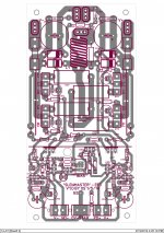
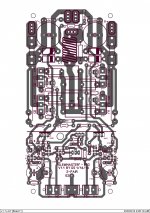
these are all the files (sprint layout file,pcb in pdf,components vie).it is based on version 1.0 sprint layout file you posted. i didnt take into account the "ghost resistor" error -V1.0 ,so i will edit version 1.1 for 2 output pairs and use that as you suggest. can you post the sprint layout file of V1.1? or modify it if you have time for 2 output pairs?
Attachments
The enclosure would have a vent for the bass/mid speaker but I'm not sure that you are moving much volume of air in a port, more of an oscillation of the air I would think. I have never tried to measure the actual turnover of the air inside of a vented speaker enclosure. The enclosure is 1/4" thickness urethane foam so would be highly insulated over the major surface area. The heat sink is not insulated except on the edges by the way it is mounted to the enclosure. The majority of the surface is exposed internally and completely externally. I was looking for just a ballpark of the internal heat rise with an output power of a total of max 90 watts.
Bottom line, you can't put the heat sink inside such a box. It will likely overheat and self destruct in a rather short time of working in the worst case conditions.
Large power subwoofers use class D, and rightly so. At (subwoofer) low frequencies, you can't beat class D.
these are all the files (sprint layout file,pcb in pdf,components vie).it is based on version 1.0 sprint layout file you posted. i didnt take into account the "ghost resistor" error -V1.0 ,so i will edit version 1.1 for 2 output pairs and use that as you suggest. can you post the sprint layout file of V1.1? or modify it if you have time for 2 output pairs?
Post # 348 is V1.1.
edit- you wanted the sprint .. below.
OS
Attachments
Last edited:
Waly,
The heatsink is not inside the box, it is the rear surface of the enclosure, completely exposed to the inside and the outside except for the edges that are attached to the enclosure, about 1/4" around the back edge only. I was thinking of an external power supply, perhaps a switch mode power supply. It doesn't sound from Ostripper's information that the internal heat would be excessive or even very much. 90 watts total will be in the 100+db range of output, so not a problem with power output.
The heatsink is not inside the box, it is the rear surface of the enclosure, completely exposed to the inside and the outside except for the edges that are attached to the enclosure, about 1/4" around the back edge only. I was thinking of an external power supply, perhaps a switch mode power supply. It doesn't sound from Ostripper's information that the internal heat would be excessive or even very much. 90 watts total will be in the 100+db range of output, so not a problem with power output.
Waly,
The heatsink is not inside the box, it is the rear surface of the enclosure, completely exposed to the inside and the outside except for the edges that are attached to the enclosure, about 1/4" around the back edge only. I was thinking of an external power supply, perhaps a switch mode power supply. It doesn't sound from Ostripper's information that the internal heat would be excessive or even very much. 90 watts total will be in the 100+db range of output, so not a problem with power output.
I'm putting one of these in my logitech Z-5500 10" sub. The heatsink fins
face outside and are 8 X 8" X 1.5. I'm putting the trafo + PS inside. Same as logitech did. It is vented with a 3" port.
As long as that main HS is facing out , all else will just be trafo losses ,
the bridge and other single digit wattage devices - no issue (with a port).
OS
The heatsink is not inside the box
Then you should be, most likely, fine.
Estimating the internal temperature is still very difficult. Theoretically, if the case is adiabatic, even the lowest power dissipation inside would, over time, increase the temperature, without any limits (it may explode before it melts, though 😀), cf. P*t=m*c*dT where P is the dissipated power, t is the time, m is the air mass inside the case, c is the heat capacity of air ( 1.0035 J/(gram/K) ) and dT is the temperature rise.
In practice, a case is never adiabatic, so some heat is lost, therefore the temperature would stabilize at a certain value, where the rate of heat generated by the internal sources equals the rate of heat loss from the case. As I said, it is very hard to estimate this analytically, since the heat losses from your case are unknown.
Thanks,
Ostrippeer, makes me think I'm not crazy then as you will be using higher output and a larger power supply. About the same heat sink area except for the height and I don't know if you are including the total thickness or only the height of the fins. Now I only need a complete circuit design with active crossovers and EQ and I'm home free! haha.
Ostrippeer, makes me think I'm not crazy then as you will be using higher output and a larger power supply. About the same heat sink area except for the height and I don't know if you are including the total thickness or only the height of the fins. Now I only need a complete circuit design with active crossovers and EQ and I'm home free! haha.
Thanks Waly,
With an open port there would always be a heat transfer through that point and it would try to equalize as much as possible though you would still have some heat rise above ambient temp. I think I have my answer that what I am attempting is reasonable. My prototype speaker design was in a larger enclosure and using and integrated H/K amplifier with 90 watts total through passive 4th order L/R crossovers you could barely stay in the same room, loud was the operative word.
With an open port there would always be a heat transfer through that point and it would try to equalize as much as possible though you would still have some heat rise above ambient temp. I think I have my answer that what I am attempting is reasonable. My prototype speaker design was in a larger enclosure and using and integrated H/K amplifier with 90 watts total through passive 4th order L/R crossovers you could barely stay in the same room, loud was the operative word.
Hi Uncle Os, i use blue bright led but i measure VF for minimum 2.8v and Red led for minimum 1.8V as you specified.
Thanks
Thanks
Hi Uncle Os, i use blue bright led but i measure VF for minimum 2.8v and Red led for minimum 1.8V as you specified.
Thanks
2.8v is close to the 3V (UV/violet led). In fact , if you feel the need for more
amplitude .... green at 2.1V will work as well for the Hawksford. 2.1v to 3.2V is
the target for the cascode.
The reds at 1.8v are correct , simulation shows 1.77Vf giving 1.6ma at the
CCS's.
Measure your zener voltages (12.2 or close) , both capacitance multipliers
should be within .2-.3V of each other. Your IPS is balanced ...only 16ma
per rail.
Since your bias was successful , I assume your VAS is at 4.5ma ... the leds
use another 2-3ma .. so about 6-7ma should be drawn across the VAS Re's.
OS
NAF , If you give me the rails Voltages you use, I will plug it in to LT and
give you a detailed Voltage schema you can check with. LT should be
within mV and mA of your real IPS. 🙂
OS
give you a detailed Voltage schema you can check with. LT should be
within mV and mA of your real IPS. 🙂
OS
Thank you very much for explanation2.8v is close to the 3V (UV/violet led). In fact , if you feel the need for more
amplitude .... green at 2.1V will work as well for the Hawksford. 2.1v to 3.2V is
the target for the cascode.
The reds at 1.8v are correct , simulation shows 1.77Vf giving 1.6ma at the
CCS's.
Measure your zener voltages (12.2 or close) , both capacitance multipliers
should be within .2-.3V of each other. Your IPS is balanced ...only 16ma
per rail.
Since your bias was successful , I assume your VAS is at 4.5ma ... the leds
use another 2-3ma .. so about 6-7ma should be drawn across the VAS Re's.
OS
"Current feedback will "dump" +/- 50ma or more into the clean ground"
Yes, this can be an issue - only way to solve it is to keep the return track separate back to the board star ground. I agree this is not an issue in VFA designs.
However, just one more challenge to be solved!
Very nice looking boards BTW - I've picked up quite a few tips from your efforts here.
Yes, this can be an issue - only way to solve it is to keep the return track separate back to the board star ground. I agree this is not an issue in VFA designs.
However, just one more challenge to be solved!
Very nice looking boards BTW - I've picked up quite a few tips from your efforts here.
I want transistor for thermal compensation that assembled on main heat sink is plastic and cheap. I found any kind of TO-126 that low Cob and high VCEO is expensive. Can you suggest me what transistor should I use?
Beautiful board!Hello uncle Os,
I've finished my Slewmaster build need to connect FB to IPS,
what is the best way to connect NFB?
Thank you
Can you share the input board(pdf)?
Thanks.
Thimios.
- Home
- Amplifiers
- Solid State
- Slewmaster - CFA vs. VFA "Rumble"