No problem ... thank you very much it solved.. i'll fix my build.
But the sound its wonderfull
Wait till you reduce VAS mA , THD is 1/4 at the correct 4.4mA vs
the "hot" 7-8 you were/are running.
Hawksford cascode , when I built it (luxman VFA) .... had the best vocal
representation of all my VAS's.
It should be awesome with your CFA 😎 .
OS
Hi Ostripper i'm happy to try all versions!Which ones ??
I have the VFA wolverine and the CFA nad1.1 (servo).
os
Best regards.
Thimios.
Hi Ostripper i'm happy to try all versions!
Best regards.
Thimios.
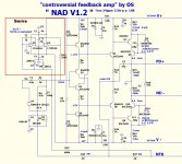
Wait till I update the NAD. NAF was so kind to prototype , now I
know how to perfect it. (V1.2)
Then I will post both (might "tweak" the wolverine , too)
Soon ,in the near future .... the VFA "symasui" and the new CFA-X
We will have 4 IPS's !!
OS
Ok waiting fo this.Wait till I update the NAD. NAF was so kind to prototype , now I
know how to perfect it. (V1.2)
Then I will post both (might "tweak" the wolverine , too)
Soon ,in the near future .... the VFA "symasui" and the new CFA-X
We will have 4 IPS's !!
OS

I can start with the output board.
Good luck.
Thimios.
Last edited:
I assume it is because with CFA , we are "mixed" ... a current derived
NFB vs. a voltage derived input signal.
Dumping the CF signal to the lifted ground modulates that ground reference.
THD suffers (this seems to be degenerative FB).
The VFA (like the Badger), I DO feed the DC cap back to the lifted ground.
NO THD degradation. (just uA FB current here)
What is different here ... we are differentiating two voltages.
I haven't exactly figured out why , but the manufacturers also do this ...
and the simulator backs up these differences. (lowest distortion)
OS
Yes, you are right - the signal mode is mixed with voltage input on the + input and a low Z current port on the - input.
The 'lifter' Is an old trick used to raise the IP impedance IIRC. I would have to sim to be sure. However, I always include a lifter of 10 ohms purely to isolate the FE GND. The lifter forces the signal GND return to be referenced to the GND star rather than through the ground on the amplifier PCB and then back to GND star ( you have to run a connection from the phono input socket to the star GND for this scheme to work).
In most cases I don't need to short it out - and as you say with VFB the currents are low enough (because the FB resistors are higher in value) for it to not be a concern. But of course on CFA you have to be careful.
Last edited:
Hello Uncle Os,
I'm reporting my build .. it fix now.
Supply 56Vdc
Stable bias at 25.4mV across RE and very easy to set
Stable dc offset below 1.5mV
Warm Vas 1.5V at R21/R17
And sound is Wonderfull!
Congratulation!
I'm reporting my build .. it fix now.
Supply 56Vdc
Stable bias at 25.4mV across RE and very easy to set
Stable dc offset below 1.5mV
Warm Vas 1.5V at R21/R17
And sound is Wonderfull!
Congratulation!
Hello Uncle Os,
I'm reporting my build .. it fix now.
Supply 56Vdc
Stable bias at 25.4mV across RE and very easy to set
Stable dc offset below 1.5mV
Warm Vas 1.5V at R21/R17
And sound is Wonderfull!
Congratulation!
VAS at 10ma Re ? Main cascode must be 5.5 - 5.8ma ... this is within range.
OPS is designed for 4 - 6+ ma VAS currents.
Your (red led)CCS's must have a little more current than simulated (1.8+ mA).
Still , all is within design parameters. I design with a lot of "play" , so
the circuit will work VERY well -- regardless of unknown devices.
You say it "sings" very well ??
Then I will "lock down" the final "NAD V1.2" IPS schema (below).
"CFA "deluxe" 😀
PS - 2 days off ... I will streamline ALL OPS's (2 -3 - 5pair)
and I might even add an IPS (CFA)to the lineup !!
OS
Attachments
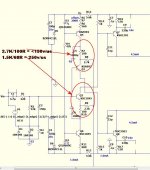
OS, what do you think about this IPS? It is almost same as your glacfa2.
I can improve the slew rate a bit if I run pre and driver transistor "hotter".
More slew rate is more current 😱
The OPS running a little "hotter" in your sim increases slew slightly.
Running the VAS at 10ma - slightly....
ON a CFA , higher IP stage CCS current/ increased current FB (lower R for current feedback resistors) will dramatically increase slew (below).
Even with a low I VAS (4.6ma) ....
OS
Attachments
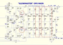
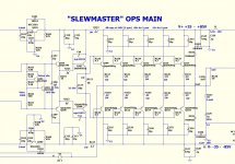
"unified" OPS (5/3/2 pair) ...
"Slewmonster (5 pair) is done (below 2).
- added a C-B shunt for drivers (Bimo 🙂 ) ... they are "Csa/Csb" ,
either a straight pF or R/C shunt of driver pair. OPS can now
be used universally for any EF3 configuration without modification.
-universal OP Re's all around.
-universal schematic for all 3 OPS PCB's ... omit last 2/3 pair for
smaller OPS PCB's. (below 1).
-The 2 pair board will have toshiba or MJE15032/33 (to-220) drivers. It will
be capable of being an EXACT clone of the H/K 680R OPS (105w/8R - 52V rails).
-Single sided for easy DIY (toner transfer) !
2 and 3 pair EF3 will be the same exact circuit as the 5 pair - no confusion
in troubleshooting or discussions. 🙂
Finished package will have BOM/screen/copper/schema/sprint file -all 3 OPS's.
Also a short "write-up" text file .... construction tips !
PS - final PCB size 5-7-9 X 3" (125/175/225 X 76mm)
OS
Attachments
More "gifts" ...
The CRC below ....
- either 10mm or 4 pin snap-in capacitors.
- 10A "barrel" diodes (6A10 or 10A10) or to-220 15-25A devices.
- made for class AB , CRC - "R" will be 1 or 2 (stacked) 1R 5W units ,
2 pairs of diodes in middle ... their Vf will bypass the "R" at high currents.
- use hardware flat stock for diode HS's (no special stuff required).
- bleeder R , leds , .1u bypass and Diode snubbers.
- 40K uf total 80V
I won't buy the cheap Ebay PS's - I want this.
PS - I have one of these for my test PS already ... 5 years old !
OS
Attachments

"Slewmonster (5 pair) is done (below 2).
- added a C-B shunt for drivers (Bimo 🙂 ) ... they are "Csa/Csb" ,
either a straight pF or R/C shunt of driver pair. OPS can now
be used universally for any EF3 configuration without modification.
-universal OP Re's all around.
-universal schematic for all 3 OPS PCB's ... omit last 2/3 pair for
smaller OPS PCB's. (below 1).
-The 2 pair board will have toshiba or MJE15032/33 (to-220) drivers. It will
be capable of being an EXACT clone of the H/K 680R OPS (105w/8R - 52V rails).
-Single sided for easy DIY (toner transfer) !
2 and 3 pair EF3 will be the same exact circuit as the 5 pair - no confusion
in troubleshooting or discussions. 🙂
Finished package will have BOM/screen/copper/schema/sprint file -all 3 OPS's.
Also a short "write-up" text file .... construction tips !
PS - final PCB size 5-7-9 X 3" (125/175/225 X 76mm)
OS
Thank you, OS. Now, I understand about slew rate in CFA. 2EF can have more slew rate and more distortion than 3EF.
On my 3EF PCB, I add option for the driver. I can use TO-220 or TO-3P/TO-264. For compensation, I add option, C for pre-driver or C-R for driver.
OS thanks for all your hard and excellent work.
Two quick questions, what VA for a monoblock Slew Monster @85V(maybe you could recommend a transformer from AnTek ) maxed out.
How long in minutes does it take you to IRON on the toner transfer from your HP printer to a board? I bought a HP 2100 on your recommendation, thanks for tip. Can others here say how long it takes to do the IRONING? It seems to take for ever for me to get a good image transfer. I am trying to see if I am doing something wrong.🙁
I'm impressed! I will be sure to build a couple of channels. Thank you!!
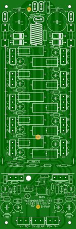
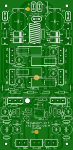
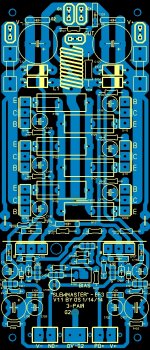
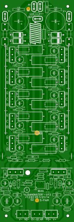
Wait for the "housekeeping" (which I'm doing).
It's harder than I thought (below 1-4)
Going from 5 -pair to 3 , each extra pair has to have numbers in
groups of 4 (2 re's and 2 basestoppers) to "jive" with the unified
schematic ... argggg !
There, all 3 and the schema .. ahhhh !
Still have to swap to-220 for the "baby" (first one).
If anyone wanted a 10pair, or something ... let them "have at" the
sprint file. These should do for most.
Ha ... we have the "monster, master, and the baby" ... 😎

PS - final scaling resulted in these dimensions - 6.125/7/9 X 3"
(155/177/225 X 76.2mm)
OS
Attachments
Last edited:
OS thanks for all your hard and excellent work.
Two quick questions, what VA for a monoblock Slew Monster @85V(maybe you could recommend a transformer from AnTek ) maxed out.
How long in minutes does it take you to IRON on the toner transfer from your HP printer to a board? I bought a HP 2100 on your recommendation, thanks for tip. Can others here say how long it takes to do the IRONING? It seems to take for ever for me to get a good image transfer. I am trying to see if I am doing something wrong.🙁
Crank that iron up ... all the way. Pressing down real hard , I can get it in
about 2 or 3 passes.
You will see the pattern raise up slightly through the paper.
I'll even "preheat the board" a little with the iron to the backside.
PS - we should ask NAF .... his "master" looked awesome , even the
screenprint. I always screwed this up 😱 .
EDIT - the "monster" - get this .... http://www.antekinc.com/an-5464-500va-64v-transformer/ ahhhh ' site redesign !! 64-0-64 about 82-83v rails - 500w amp/4R - for real , I left
the "bus bar"(big copper wire) on the 5 pair - 12-15A fuses !!!
OS
Last edited:
Hi Ostripper
greetings have all parts for this wonderful amp only KSC3503 very hard to get here any subtitute transistor i can use this amp is on my mind for a long time
warm regards
andrew
greetings have all parts for this wonderful amp only KSC3503 very hard to get here any subtitute transistor i can use this amp is on my mind for a long time
warm regards
andrew
Hi Ostripper
greetings have all parts for this wonderful amp only KSC3503 very hard to get here any subtitute transistor i can use this amp is on my mind for a long time
warm regards
andrew
As I said , much "play" in my designs. the good ol' 340/350 will do for
just about any to-126 device in my designs. BDxxx for vbe ,
any of the toshiba 2sa/sc with decent hfe/+ 160V+ vce will do for the VAS.
I've swapped many models into both the OPS-IPS sim's with minimal THD
degradation / change in operating points ! 🙂
Very" forgiving" designs (especially the NAD CFA )
OS
Hi Ostripper
greetings thats good news i will make the pcb today
warm regards
andrew
The "master" (3- pair) is posted earlier in this thread. It is the most perfected
of the 3 ....
Do you want the monster (5 -pair) ? (it's done).
pS - look for v1.2 of anything ... these are SOTA.
OS
Last edited:
- Home
- Amplifiers
- Solid State
- Slewmaster - CFA vs. VFA "Rumble"