hello Thimios here http://www.diyaudio.com/forums/solid-state/248105-slewmaster-cfa-vs-vfa-rumble-14.html#post3774372Beautiful board!
Can you share the input board(pdf)?
Thanks.
Thimios.
Bimo, try BD139/140
Right now I use BD139 (it mount under PCB), but it is not all plastic. I must use insulator, because I use metal spacer.
Thanks friend which schematic matching this?
Regards.
Thimios.
Bimo, try BD139/140
Hello , Sir Bonsai ...

I did back off the current a bit . Nafs CFA will just dump 20ma back
into the 2nd stage of the IPS.
And it is connected directly into the G2 (separate from the lifted ground).
OS
I want transistor for thermal compensation that assembled on main heat sink is plastic and cheap. I found any kind of TO-126 that low Cob and high VCEO is expensive. Can you suggest me what transistor should I use?
Vbe's can be low Vceo. Vbe has only the B-E spread of the EF3 across it ...
6 X .6v =<4V .
OS
Vbe's can be low Vceo. Vbe has only the B-E spread of the EF3 across it ...
6 X .6v =<4V .
OS
Yes, I know that 🙂. Currently I use BD139. But BD139 has metal body at back side. I want to the body is all plastic like KSC3503, for easy mounting. But KSC3503 is expensive.
Hi Ostripper if it's possible please place on one post schematics in&out.Pcb pdf in & out.Hello , Sir Bonsai ...
I did back off the current a bit . Nafs CFA will just dump 20ma back
into the 2nd stage of the IPS.
And it is connected directly into the G2 (separate from the lifted ground).
OS
Thanks.
Last edited:
Hi Ostripper if it's possible please place on one post schematics in&out.Pcb pdf in & out.
Thanks.
Which ones ??
I have the VFA wolverine and the CFA nad1.1 (servo).
os
Thanks friend.🙂Thimios, my build is cfa on post #111
NAD-H IPS
Just now i see in post 118 Ostripper say about an error in this vers.1.0
Last edited:
Hello , Sir Bonsai ...
I did back off the current a bit . Nafs CFA will just dump 20ma back
into the 2nd stage of the IPS.
And it is connected directly into the G2 (separate from the lifted ground).
OS
Ahhh - problem solved!
😎
KSC3503 $0.4 , Rp5000, very expensive 😀
Didiet
Didiet, it is still expensive for me.
If I can use cheap part without sacrifice the quality, I will very happy 😀. I always want to make design with high price/performance. It is more challenging.
Bonsai, I still do not understand how to improve slew rate in CFA. I follow the discussion about CFA, I think the slew rate can be increase if we lowered resistance of feedback resistor. But in my simulation, it is not so easy. May be another variables involve here.
Last edited:
Didiet, it is still expensive for me.
If I can use cheap part without sacrifice the quality, I will very happy 😀. I always want to make design with high price/performance. It is more challenging.
Bonsai, I still do not understand how to improve slew rate in CFA. I follow the discussion about CFA, I think the slew rate can be increase if we lowered resistance of feedback resistor. But in my simulation, it is not so easy. May be another variables involve here.
Post the simulation (.asc) where you get sub-optimal slew. With either
NAF's NX or my new VSSA clone , I get 200V/us+ ... always , even
with reduced current in the FB divider.
Always 2-3 X what I get with the best VFA's !
OS
Hi uncle Os, yesterday i supply with 39vdc for testing.
Bias ok, i can set for 60mA a cross RE, dco stable below 2mv
Now i supply with 56vdc and i can't set the bias for 60mA across Re. I turn bias trim to minimum and it stay atv70mV (150mA)...it's very hot
Please would you simulate it so i can set bias for 60mA cross RE
Bias ok, i can set for 60mA a cross RE, dco stable below 2mv
Now i supply with 56vdc and i can't set the bias for 60mA across Re. I turn bias trim to minimum and it stay atv70mV (150mA)...it's very hot
Please would you simulate it so i can set bias for 60mA cross RE
Ahhh - problem solved!
😎
I assume it is because with CFA , we are "mixed" ... a current derived
NFB vs. a voltage derived input signal.
Dumping the CF signal to the lifted ground modulates that ground reference.
THD suffers (this seems to be degenerative FB).
The VFA (like the Badger), I DO feed the DC cap back to the lifted ground.
NO THD degradation. (just uA FB current here)
What is different here ... we are differentiating two voltages.
I haven't exactly figured out why , but the manufacturers also do this ...
and the simulator backs up these differences. (lowest distortion)
OS
Hi uncle Os, yesterday i supply with 39vdc for testing.
Bias ok, i can set for 60mA a cross RE, dco stable below 2mv
Now i supply with 56vdc and i can't set the bias for 60mA across Re. I turn bias trim to minimum and it stay atv70mV (150mA)...it's very hot
Please would you simulate it so i can set bias for 60mA cross RE
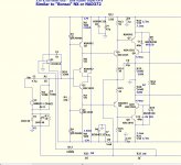
I already figured out why ! 🙂
look to your hawksford VAS. My original schema shows 68R for the Re's.
I messed up ! 😱😱
TOO much current !
Reduce VAS mA ....
Change R17/21 to 150R and R18 to 47K.
This will set 7.1ma total across R17/21 , the leds will drain off 2.7ma ...
leaving the main VAS cascode at 4.4ma.
Doing this will make for the 60ma OP bias at just about exactly half way
(205R out of the 500R trimmer).
I got these readings with my standard 60V rail simulations ... sorry for
mistake.
PS - another combo that will work is 120R = R17/21 (8ma total) reduce R18 to 27K
(brighter leds = 3.7ma) ... leaving 4.3ma at main Cascode !!
OS
Attachments
Last edited:
I already figured out why ! 🙂
look to your hawksford VAS. My original schema shows 68R for the Re's.
I messed up ! 😱😱
TOO much current !
Reduce VAS mA ....
Change R17/21 to 150R and R18 to 47K.
This will set 7.1ma total across R17/21 , the leds will drain off 2.7ma ...
leaving the main VAS cascode at 4.4ma.
Doing this will make for the 60ma OP bias at just about exactly half way
(205R out of the 500R trimmer).
I got these readings with my standard 60V rail simulations ... sorry for
mistake.
OS
No problem ... thank you very much it solved.. i'll fix my build.
But the sound its wonderfull
Post the simulation (.asc) where you get sub-optimal slew. With either
NAF's NX or my new VSSA clone , I get 200V/us+ ... always , even
with reduced current in the FB divider.
Always 2-3 X what I get with the best VFA's !
OS
I try to sim several CFA, with and without diamond buffer input. The highest slew rate is around 200 V/uS, except the original NX-amp is 1100 V/uS.
I sim Bonsai's e-Amp (VFA) IPS with my 3EF, I get 220V/uS.
Last edited:
No problem ... thank you very much it solved.. i'll fix my build.
But the sound its wonderfull
I use 14mA current in VAS. Bias current is no problem 😎.
Hi Naf, can you compare the sound with other amp that you built? I know you make PeeCeeBee, Honey Badger, etc.
- Home
- Amplifiers
- Solid State
- Slewmaster - CFA vs. VFA "Rumble"