Probably an optical illusion, but the board appears to be askew on the heatsink. Wouldn't the template help to get things lined up straight?
That is a scrap piece of aluminum being used as a jig and not a heatsink. As such I don't have any concerns if it is askew. On a heatsink I would take care to align it properly.
Seems getting a jig properly aligned would be even more important since errors tend to amplify. Aligning the jig onto the heatsink would be much more difficult with skewed boarders. Sorry, I did layout for years. My mind is skewed. 😀
The jig is not intended to assist with preparing the heat sink, just with the assembly of the electronics. I would print another template and punch and drill it in a separate operation.
Sorry if I wasn't clear in my suggestion for making assembly easier. Seems I've had the opposite effect 🙁.
Sorry if I wasn't clear in my suggestion for making assembly easier. Seems I've had the opposite effect 🙁.
Lol,
Sorry, I made assumptions. I thought the jig was to be used for both.
How do you create the printout?
Sorry, I made assumptions. I thought the jig was to be used for both.
How do you create the printout?
Terry,
I'm with you if I was going to do a drill jig I would use some sort of alignment pins and some drill bushings if I was going to do serial production or just set up a cnc program with a fixture.
I'm with you if I was going to do a drill jig I would use some sort of alignment pins and some drill bushings if I was going to do serial production or just set up a cnc program with a fixture.
Lol,
Sorry, I made assumptions. I thought the jig was to be used for both.
How do you create the printout?
I use a 2-D CAD program, Qcad, for laying out templates and such. It is cheap to buy the full version (or at least it was, haven't checked in a while) and there is a 'free' version that does almost everything that the full version does as well.
Terry,
I'm with you if I was going to do a drill jig I would use some sort of alignment pins and some drill bushings if I was going to do serial production or just set up a cnc program with a fixture.
Serial production is something totally different. Most of us will only need to prep a pair of heat sinks, so a paper template, a centre punch and a drill press will serve most quite nicely.
Now getting over 10 pieces makes doing something more elaborate reasonable.
This is probably just me, but if I am going to the trouble of drilling and tapping a jig for aligning the transistors, I would want to use that same jig for aligning the holes in my heatsink.
Thanks for the print template Jason. I'm going to make a template. I hate it when I get done and the outputs aren't exactly straight.
Blessings, Terry
Thanks for the print template Jason. I'm going to make a template. I hate it when I get done and the outputs aren't exactly straight.
Blessings, Terry
Your right Jason.
I just have to plan for a production application. More than likely it will be cnc as I have to machine holes for the mounting of the heat sink and the output devices.
I just have to plan for a production application. More than likely it will be cnc as I have to machine holes for the mounting of the heat sink and the output devices.
No, this isn't a modifyed board .It's another new board.Thimios, One of those eight legged devices and a few things and you can tell us how it sounds. Did you just modify the V1.2 and turn it into the V1.3 or is this another board. Can't wait to hear how it sounds.
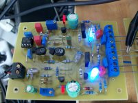
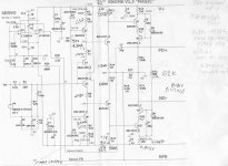
Boys and girls here is Gnome V1.3!
Nice ! Good to see the spacing in real life (I allowed more).
You DO need to have a higher wattage FB resistor( R17).
OS
This is probably just me, but if I am going to the trouble of drilling and tapping a jig for aligning the transistors, I would want to use that same jig for aligning the holes in my heatsink.
Thanks for the print template Jason. I'm going to make a template. I hate it when I get done and the outputs aren't exactly straight.
Blessings, Terry
i use a 1/16 inch thick cardboard as drilling template using Jason's template printed on a bond paper and then pasted onto the thick board..
a pointed tool such as a pin to make indents on the cross-hairs, and then start drilling with a 1mm drill on the template thence to the heatsink, no need to drill all the way thru, just enough to make a deep indent...
you can then proceed to drill to desired hole diameter....
btw, this is also how i do 1 off board runs...and most of what i do are 1 offs..... 😀
Boys and girls here is Gnome V1.3!
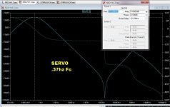
To make you happy .... If you only have 1u for the servo caps (C10/11)
(you have some mounted below) , increase R26-27 to 1meg.
With 1meg/1uf = .37hz Fc , still good to go.
OS
Attachments
OS, thanks for all.Especialy thanks for your investigations.
This is a weekend try ,not a final board.
I couldn't wait for all recommended parts.
Regards.
Thimios
This is a weekend try ,not a final board.
I couldn't wait for all recommended parts.
Regards.
Thimios
Last edited:
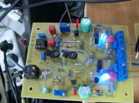
 Gnome V1.3 first try.
Some resistors must be changed values ,my opinion.
OS, here you are the Boss.😉
Attachments
Last edited:
Not yet, my friend we must trim some resistors first.😉nice work thimios!!!sound impressions?? square wave response + clipping response?
Hi Thimios,
you're so fast 🙂
I'm too slow to build, even my OPS boards not full stuffed yet...
(some larger parts can't fit on the board)
I think I should try this Gnome first 😀
tomorrow will be "Silence Day" in my Island, so no activities 😀
you're so fast 🙂
I'm too slow to build, even my OPS boards not full stuffed yet...
(some larger parts can't fit on the board)
I think I should try this Gnome first 😀
tomorrow will be "Silence Day" in my Island, so no activities 😀
Some resistors must be changed values ,my opinion.
OS, here you are the Boss.😉
Yes , maybe 680-820R for R13/16. With the new trimmers , R5/R10 ....
If you make the "safety" resistors small (R6/9 - 330R) , R5/10 should
give you a wide range of input device current allowing you to set your VAS
current perfectly ! 😎
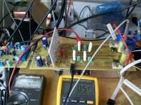
Good to see the .5mv servo controlled DC value !
Also , with the trimmers , feel free to bias those VAS leds to taste
( 33k - 68k).
PS - I design at 70-85V , you build at 40-50V .... so , there will be some
variation (R11-12 -zener regs.)
Good work !!
OS
- Home
- Amplifiers
- Solid State
- Slewmaster - CFA vs. VFA "Rumble"