Jason.
Perhaps OS was talking about using film caps to bypass the lytics but I don't know. I have never heard that an electrolytic cap was superior to a film cap except for physical size myself, perhaps this is something new to learn where a lytic is superior to a film cap in a specific instance. Cost is another factor normally used to justify not using a film cap.
Perhaps OS was talking about using film caps to bypass the lytics but I don't know. I have never heard that an electrolytic cap was superior to a film cap except for physical size myself, perhaps this is something new to learn where a lytic is superior to a film cap in a specific instance. Cost is another factor normally used to justify not using a film cap.
Thimios,
That looks pretty ugly. Could that be an RF problem or high frequency oscillation causing all that hash? What happens if you put a low pass filter on the input?
That looks pretty ugly. Could that be an RF problem or high frequency oscillation causing all that hash? What happens if you put a low pass filter on the input?
Measurments after updates.
The instability remain.
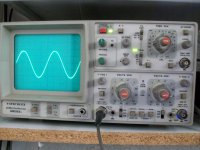
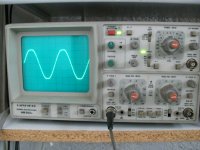
Amplifier oscillates after clipping also, (sinusoidal wave test)
I measure 2mv A.C on out even when input is sorted but can't hear any noise from speaker.
Check your C7 , on your 1.2 you used a ceramic 33p ... I don't know
what clear/silver cap you have now ?
If that don't work , reduce (or remove/jumper) R20/24 ... you
then basically have V1.2 again (except for inv. servo).
That 2 mv ac is oscillation at very HF. Does the OPS zobel get warm ?
OS
I have already tried another 39pf ceramic typ ,same results.Check your C7 , on your 1.2 you used a ceramic 33p ... I don't know
what clear/silver cap you have now ?
If that don't work , reduce (or remove/jumper) R20/24 ... you
then basically have V1.2 again (except for inv. servo).
That 2 mv ac is oscillation at very HF. Does the OPS zobel get warm ?
OS
I keep generator's level low ,so zobel isn't warm.
Is any useful ,to measure this output with a frequency counter?
Last edited:
I have already tried another 39pf ceramic typ ,same results.
I keep volume low,so zobel isn't warm.
Is any useful ,to measure this output with a frequency counter?
The 1.3 is basically the 1.2.
What we changed is the 2 extra resistors.. r20/24,added the trimmers ,
and changed servo style.
Even the PCB traces are almost the same.
So ,
step 1 -remove the resistors
step 2 - blue leds .. you used green before.
just "backtrack" to V1.2 , read output ... see what change gets
you stable again.
Are you using the same parts (active devices) as before ?
The only way I could reproduce your ringing was to drop C7 to 10pF.
OS
Are you using the same parts (active devices) as before ?The 1.3 is basically the 1.2.
What we changed is the 2 extra resistors.. r20/24,added the trimmers ,
and changed servo style.
Even the PCB traces are almost the same.
So ,
step 1 -remove the resistors
step 2 - blue leds .. you used green before.
just "backtrack" to V1.2 , read output ... see what change gets
you stable again.
Are you using the same parts (active devices) as before ?
The only way I could reproduce your ringing was to drop C7 to 10pF.
OS
Inp A970 C1815 ,A970,C1845 for driver to vas
Instability increased after last update,SEE POST #1476 Vac out=0.3mvA.C, now is 2mV A.C
I will try to jumper these 4R7 and report again later
Last edited:
Are you using the same parts (active devices) as before ?
Inp A970 C1815 ,A970,C1845 for driver to vas
Instability increased after last update.
I will try to jumper these 4R7 and report again later
Another drastic "backstep" .... just pull the servo IC ... that will
eliminate that change as a problem. offset should only be 1V.
"A970/C1815" ??? as your P/N pair ?
A970 = hfe 500-700 C1815 = could be as low as 70. Quite a mismatch !
Also try using the green leds again. 😕
OS
I have measure hfe tcsa970=200,c1815gr=280Another drastic "backstep" .... just pull the servo IC ... that will
eliminate that change as a problem. offset should only be 1V.
"A970/C1815" ??? as your P/N pair ?
A970 = hfe 500-700 C1815 = could be as low as 70. Quite a mismatch !
Also try using the green leds again. 😕
OS
Jason.
Perhaps OS was talking about using film caps to bypass the lytics but I don't know. I have never heard that an electrolytic cap was superior to a film cap except for physical size myself, perhaps this is something new to learn where a lytic is superior to a film cap in a specific instance. Cost is another factor normally used to justify not using a film cap.
The problem with film caps is that they resonate at high Q with the inductance of even very short traces leading to them. I've measured this resonance and it's almost impossible to get rid of it unless you use small lytics with just the right ESR. However those traces are so long, the inductance is much larger than in the situations I have dealt with, so I'm not sure which range is appropriate. I think that Nichicon HE OS pointed out is a good bet if you want to parallel with 470nF or more (33-56u), or if you don't want to use any films.
If you have a signal generator you can probe the resonance directly and test out different junk caps to find out exactly what value of ESR you need. Otherwise ESR values in datasheets may not be accurate and you may not get the right value.
At any rate, any low-ESR 100V 33u-56u lytic there will be better than nothing.
I have measure hfe tcsa970=200,c1815gr=280
I even added large inductances to ground to simulate traces ... everything.
My high gain Zetex models showed ringing (2.7 mhz UG point - less margin)
- changed R7/8 and R14/15 to 68R -all fixed.
As I said ,pull the servo ... go back to green VAS leds. If any of these 3
things does the job , we can proceed from there.
PS - the PCB layout is exactly the same for the gain stages , CCS's are about in the same place
Actually , better grounding with input and regulators on separate grounds.
Just the VAS resistors , trimmers , and servo are different. I suspect a component.
Edit - what sets the stability margin/UG is the 4 resistors (Re) at the 2 current stages , C7 (comp.cap)
and the feedback ratio .... the only other variable is the device gain.
OS
Last edited:
Previously i have had issues with noninverting servo, It lets HF through, specs are better with inverting servo(s)
Previously i have had issues with noninverting servo, It lets HF through, specs are better with inverting servo(s)
I actually left this option open for the V1.3 (gnome).
I get the EXACT same results (invert/non-inverting).
Thimios , on the gnome ... change C10 to .1 - .22u (instead of 2.2u) , this reduces Servo HF FB
greatly ... just another " tweak" .
OS
Last edited:
On the Genome, you can improve with by lowering the R39 resistors, I go down to app 10 ohms. and fit an inverting servo.
On the Genome, you can improve with by lowering the R39 resistors, I go down to app 10 ohms. and fit an inverting servo.
That was Bonsai's NX problem , he used 15R there and could not deal with
offset.
OS
My servo only works with a few mV,. But I have also inserted a 12 V cascode, this makes it possible to use low COB NPN/PNP matched doubles for the pair.
I haven't change c10 to .1 or .22.I actually left this option open for the V1.3 (gnome).
I get the EXACT same results (invert/non-inverting).
Thimios , on the gnome ... change C10 to .1 - .22u (instead of 2.2u) , this reduces Servo HF FB
greatly ... just another " tweak" .
OS
I used 1uf//1uf for c10 & 1uf//1uf for c11.
Now ,i tried all these recommented changes.
1) tl 072(servo i.c) pulled out.Offset=20mV oscillation is present.
2) R20 R24 sorted. oscillation is present.
3)changes LED to green.oscillation is present
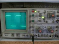
Then i try to reconfigure test set-up.
In all previous tests, my signal generator powered by 1:1 safety transformer and oscilloscope powered direct from outlet
Now i tried to power the genarator and osciloscope direct from outlet
This seems to help but not enough.
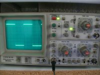
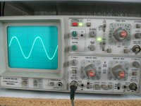
1) 26V RMS just before clipping
2)28V RMS visible clipping(Vinp=1Vrms/1KHz)
3)30V RMS
4)31V RMS
5)34V RMS
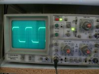
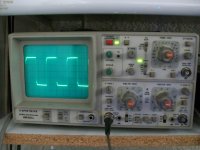
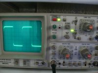
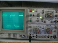
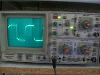
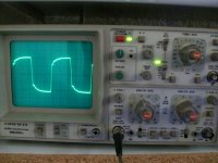
SQUARE WAVE
1)1KHz
2)5KHz
3)10KHz
4)20KHz
5)30KHz
6)50KHz
7)100KHz
8)200KHz
Attachments
-
 100_0535.JPG513.5 KB · Views: 658
 -
 100_0550.JPG541.9 KB · Views: 194
 -
 100_0549.JPG548.5 KB · Views: 181
 -
 100_0547.JPG519.3 KB · Views: 161
 -
 100_0546.JPG550.9 KB · Views: 159
 -
 100_0545.JPG537.4 KB · Views: 161
 -
 100_0544.JPG556.4 KB · Views: 551
 -
 100_0538.JPG462.6 KB · Views: 573
 -
 100_0537.JPG590.2 KB · Views: 598
 -
 100_0536.JPG605.1 KB · Views: 636
Last edited:
Thimios,
Could your signal generator be producing some RF on the output? That is why I asked if all this oscillation would go away with a simple input filter?
Could your signal generator be producing some RF on the output? That is why I asked if all this oscillation would go away with a simple input filter?
Thimios,
Could your signal generator be producing some RF on the output? That is why I asked if all this oscillation would go away with a simple input filter?
Which filter ? please give a schematic.
I haven't change c10 to .1 or .22.
I used 1uf//1uf for c10 & 1uf//1uf for c11.
Now ,i tried all these recommented changes.
1) tl 072(servo i.c) pulled out.Offset=20mV oscillation is present.
2) R20 R24 sorted. oscillation is present.
3)changes LED to green.oscillation is present
Then i try to reconfigure test set-up.
In all previous tests, my signal generator powered by 1:1 safety transformer and oscilloscope powered direct from outlet
Now i tried to power the genarator and osciloscope direct from outlet
This seems to help but not enough.
1) 26V RMS just before clipping
2)28V RMS visible clipping(Vinp=1Vrms/1KHz)
3)30V RMS
4)31V RMS
5)34V RMS
SQUARE WAVE
1)1KHz
2)5KHz
3)10KHz
4)20KHz
5)30KHz
6)50KHz
7)100KHz
8)200KHz
If you are using the to-220 drivers on your OPS , try dropping
the basestoppers (R111/R112) to a low value (2.2R) , or even jumper them.
Got rid of "glitches" when I ran close to oscillation by "tweaking" the OPS.
The compensation on the gnome is different than the spooky ,the OPS might
react differently.
OS
- Home
- Amplifiers
- Solid State
- Slewmaster - CFA vs. VFA "Rumble"