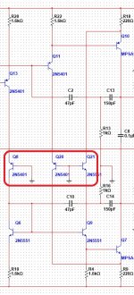
Totally agree about cascoded VAS - you can use a lower power / higher hfe transistor as VAS and higher power / lower hfe / higher voltage transistor in cascode. For example 2n5551/5401 + MPSA92/42 give a very good result.
With regards to the "upside down" 2-nd and 3-rd diff cascades advantages - I have to think a bit more why they work better... but thank you for pointing it out 😉
"upside down" = CMRR (cancellation) . Like the EMI filter for AC line.
PS - what else could explain 30db+ PSRR gain ?
OPS
Building and compared in a Weekend????thimios if you start building gnome this weekend ,please post sound differences compared to nad 1.2...
I'm not Ostripper😱
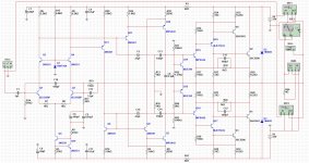
Was reading this AES paper ....
http://www.linearaudio.nl/linearaudio.nl/images/pdf/lohstroh%20pp.pdf
Looked a lot like my GLA/symasui work.
Decided to "go all the way"- (below 1-3).
Otala's paper and a (Mitsubishi) amp provided the compensation
scheme. - perfect - with phase margin to spare. The PSRR is
also stunning (110-120db without the cap mult.) !! 😀
The real cool thing is just 12 devices and I BEAT the leach - 2-5ppm
at high power. All this is OPS distortion , you would need OP stage correction
to exceed this.
This IPS running into a class A OPS has .2PPM ! (genesis OPS or looped
back without an op stage).
Otala's design rocks (below-last .ASC file) ! Same awesome British tech- (like Hawksford) 😱.
PS - another "must build" - believe me (for symasym lovers).
Edit - the slew is also "massive" !
OS

You should not forget that NFB used in an inverting amp depends on the source output impedance and is influenced by input cables. An input buffer would be a good to have here.
You should not forget that NFB used in an inverting amp depends on the source output impedance and is influenced by input cables. An input buffer would be a good to have here.
Show an example (either crude or elaborate 😀).
OS
Show an example (either crude or elaborate 😀).
OS
If you mean buffer, then you can find many good buffers in this forum. I used JLH simple buffer(search JLH buffer) with my gain clone working in inverting mode. Some will say that the buffer is not in the NFB loop, so not good.
Damir
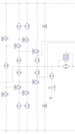
OS, did you have a chance to play with this one? I did not prototype it yet (too busy with CFA 🙂 ), but initial simulations show very good results...
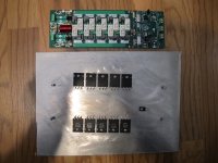
By the way, the OP showed excellent performance in simulation, but appeared very unstable in the real prototype, so I use an earlier Bryston-based design now (3-rd image attached).
By the way, the OP showed excellent performance in simulation, but appeared very unstable in the real prototype, so I use an earlier Bryston-based design now (3-rd image attached).
Attachments
You should not forget that NFB used in an inverting amp depends on the source output impedance and is influenced by input cables. An input buffer would be a good to have here.
Damir, you're absolutely right for the inverting one, but the one here is non-inverting... or am I missing something? )
If you mean buffer, then you can find many good buffers in this forum. I used JLH simple buffer(search JLH buffer) with my gain clone working in inverting mode. Some will say that the buffer is not in the NFB loop, so not good.
Damir
Oh , like just a high-z --- low Z input buffer. OP-amp non- inverting
follower ??? (as a crude example ? ).
OS
OS, did you have a chance to play with this one? I did not prototype it yet (too busy with CFA 🙂 ), but initial simulations show very good results...
By the way, the OP showed excellent performance in simulation, but appeared very unstable in the real prototype, so I use an earlier Bryston-based design now (3-rd image attached).
That technique is like the positive hawksford fb (feedforward). It adds
another pole ... like a CFP stage.
I have actually made a hawksford oscillate at 4mhz 😱 .
I tried your VAS "trick" on a few designs. No ocillation , but reduced
performance. 🙁
OS
Damir, you're absolutely right for the inverting one, but the one here is non-inverting... or am I missing something? )
I was talking about Otala amp, probably it was not clear from my post, sorry.
Show an example (either crude or elaborate 😀).
OS
He is correct. Attached are showing the difference in gain between inv. and non-inv. when driven from a source with appreciable output impedance.
Attachments

He is correct. Attached are showing the difference in gain between inv. and non-inv. when driven from a source with appreciable output impedance.
Your plot(s) did not post ?
Now that dadod elaborated 🙂 , I know what he means.
I just used Otala's paper as a "launch pad". The mitsu/symasui is
different (advanced). 😀
OS
If you placed an active opamp based crossover before one of these input section wouldn't that act as a buffer section itself? The crossover could also be run in either inverting or non-inverting if I remember correctly.

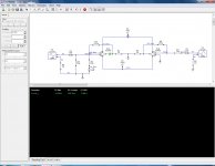
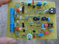
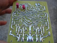
Boys and girls here is Gnome V1.3!
Attachments
Last edited:
I will PM you soon -
OS
OK, whenever you can please let me know what's up.
Thimios, One of those eight legged devices and a few things and you can tell us how it sounds. Did you just modify the V1.2 and turn it into the V1.3 or is this another board. Can't wait to hear how it sounds.
Hi Terry thanks.Dude, you are lightning in a bottle!
I believe tomorrow will fire up it.
Thimios
Assembly tips...
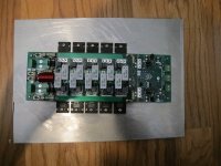
There has been some suggestion that it might be difficult to make a nice assembly. Here is what I do:
Print a paper template (make sure it is at 100% scale) and punch either a piece of aluminum as an assembly jig or the heat sink you intend to use. Drill the holes and tap them for the hardware you intend to use. Fasten your parts to the jig or heat sink. Install the board on top. Adjust lead bends if needed and solder the components to the board.
Attachments
- Home
- Amplifiers
- Solid State
- Slewmaster - CFA vs. VFA "Rumble"