Carl - there's your "leach" ... 😎
Great! And thank you!! I will run with that.
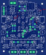
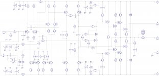
Please OS check ,is this on the right road?replace the very top jumper with 220k , bridge the X's , omit R28 ,extend R27 to "x"
and it will be V1.2 (like yours). Servo will be inverting and trimming the
diamond instead of the CF node (non-inv.)
Nice to have choices ...
Carl - there's your "leach" ... 😎
Edit - also thin trace above C10 (cut).
OS
Is this the second option?
Attachments
Last edited:
Spooky explained ...
A few non-typical things on the PCB.
1. Even as I gave "NFB" lots of clearance , with a 160V p-p setup !! 😱 ,
you might not want any signal of that level (anywhere) near the IPS.
The "anal" option ... is to run the reduced "Hi-Z". R32 and R34 can be placed
on the feedback line near the OPS , and returned at @ 4V (R32) and .1V or less
(R34).
A shielded cable can be used. NO high levels .... being a VFA , all is ideal.
2.Jumper "A". Given the choice of routing around the NFB "zone" , routing
the double sided trace or a wire (toner transfer) across the DC servo is
also (more) ideal. Everything between the 2 LTP's is low voltage/signal free.
OS
Please OS check ,is this on the right road?
Is this the second option?
Perfect , you have the V1.2. But , try the 1.3 non-inverting ... it is safer
(low-Z servo). A full servo failure (V1.3) will only give 5-6V offset.
I don't know which would sound better ? , simulation shows nearly the
same THD.
Neat , huh .... no special dual component placements.
OS
Ok Gnome or Spooky this Weekend?Perfect , you have the V1.2. But , try the 1.3 non-inverting ... it is safer
(low-Z servo). A full servo failure (V1.3) will only give 5-6V offset.
I don't know which would sound better ? , simulation shows nearly the
same THD.
Neat , huh .... no special dual component placements.
OS

Also , I forgot .... you can also offboard the "Gnome" feedback routes.
The 680K servo resistor and the 2.2K current FB resistor can be at the
OPS, too.
Extra Pads are on the servo feed trace.
On either the spooky or Gnome , even as you have a very high level signal
with the typical FB method , little current is being drawn (very little inductive
contamination).
OS
The 680K servo resistor and the 2.2K current FB resistor can be at the
OPS, too.
Extra Pads are on the servo feed trace.
On either the spooky or Gnome , even as you have a very high level signal
with the typical FB method , little current is being drawn (very little inductive
contamination).
OS
thimios if you start building gnome this weekend ,please post sound differences compared to nad 1.2...
OS,
What would it take to make the Gnome board into a complete amp with perhaps 35 watts output. Could that be done simply?
What would it take to make the Gnome board into a complete amp with perhaps 35 watts output. Could that be done simply?
OS,
What would it take to make the Gnome board into a complete amp with perhaps 35 watts output. Could that be done simply?
Cake !! But I would just go EF2 for low power like that.
Real high gain toshiba drivers paired with high gain Sanken ring emitter OP's.
OS
Sorry to pester but any chance at a zip of the IPS Sprint files? Particularly the NAD and Spooky. Much appreciated, thanks.
OS,
When your done with all your other designs it would be nice to see a schematic of a simple low powered version of the Nad to use in a bi-amp application. Don't need much power to drive a dome tweeter but it would be great to have two sections with the same basic tonality together. A super slewmaster Gnome and a Mini Gnome!
When your done with all your other designs it would be nice to see a schematic of a simple low powered version of the Nad to use in a bi-amp application. Don't need much power to drive a dome tweeter but it would be great to have two sections with the same basic tonality together. A super slewmaster Gnome and a Mini Gnome!
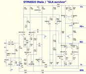
Now for the "Otala syndrome" .....
Was reading this AES paper ....
http://www.linearaudio.nl/linearaudio.nl/images/pdf/lohstroh%20pp.pdf
Looked a lot like my GLA/symasui work.
Decided to "go all the way"- (below 1-3).
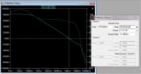
Otala's paper and a (Mitsubishi) amp provided the compensation
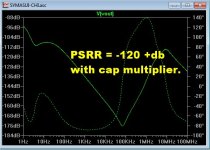
scheme. - perfect - with phase margin to spare. The PSRR is
also stunning (110-120db without the cap mult.) !! 😀
The real cool thing is just 12 devices and I BEAT the leach - 2-5ppm
at high power. All this is OPS distortion , you would need OP stage correction
to exceed this.
This IPS running into a class A OPS has .2PPM ! (genesis OPS or looped
back without an op stage).
Otala's design rocks (below-last .ASC file) ! Same awesome British tech- (like Hawksford) 😱.
PS - another "must build" - believe me (for symasym lovers).
Edit - the slew is also "massive" !
OS
Was reading this AES paper ....
http://www.linearaudio.nl/linearaudio.nl/images/pdf/lohstroh%20pp.pdf
Looked a lot like my GLA/symasui work.
Decided to "go all the way"- (below 1-3).
Otala's paper and a (Mitsubishi) amp provided the compensation
scheme. - perfect - with phase margin to spare. The PSRR is
also stunning (110-120db without the cap mult.) !! 😀
The real cool thing is just 12 devices and I BEAT the leach - 2-5ppm
at high power. All this is OPS distortion , you would need OP stage correction
to exceed this.
This IPS running into a class A OPS has .2PPM ! (genesis OPS or looped
back without an op stage).
Otala's design rocks (below-last .ASC file) ! Same awesome British tech- (like Hawksford) 😱.
PS - another "must build" - believe me (for symasym lovers).
Edit - the slew is also "massive" !
OS
Attachments
Last edited:
Sorry to pester but any chance at a zip of the IPS Sprint files? Particularly the NAD and Spooky. Much appreciated, thanks.
I will PM you soon -
OS
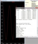
This is fun ....
NO amp I have simulated has stayed at single digit 200V p-p (below) at
any frequency like this one.
Boo - hoo.... but it goes double digit 20-30ppm at 20K /3R. 😱
A "super-duper SYM" !!
5 -pair OPS + this IPS + Semelab devices + 600VA trafo/60Kuf .... add
the 12" - prepare for oblivion.
OS
NO amp I have simulated has stayed at single digit 200V p-p (below) at
any frequency like this one.
Boo - hoo.... but it goes double digit 20-30ppm at 20K /3R. 😱
A "super-duper SYM" !!
5 -pair OPS + this IPS + Semelab devices + 600VA trafo/60Kuf .... add
the 12" - prepare for oblivion.
OS
Attachments
I will PM you soon -
OS
As a SymaSym fan I would ask you get the sprint files for the Symasui Otala to Jason as well. He's an animal on those Gerbers!
Was reading this AES paper ....
http://www.linearaudio.nl/linearaudio.nl/images/pdf/lohstroh%20pp.pdf
Looked a lot like my GLA/symasui work.
Decided to "go all the way"- (below 1-3).
Otala's paper and a (Mitsubishi) amp provided the compensation
scheme. - perfect - with phase margin to spare. The PSRR is
also stunning (110-120db without the cap mult.) !! 😀
Just noticed - the one I did based on Pioneer M3 (and thus M3 itself) is very close in principle to the one in the article. Pioneer engineers were definitely familiar with it 🙂
In any case, it's a great amp. I often use the prototype as a reference to compare the other designs' sound with it.
And a 7-channel version based on it is coming soon 😉
Attachments
As a SymaSym fan I would ask you get the sprint files for the Symasui Otala to Jason as well. He's an animal on those Gerbers!
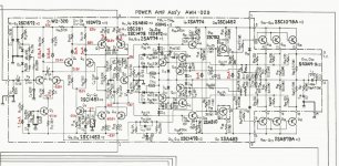
Here is the "lowdown" .
Otala seems to be the "father" of the symasym. After his 70's
paper I linked to.... is when Mitsubishi's DA-pxx series of amps
came into being (1975-80).
The Da-p10 is the amp I saw (pilfered for idea's 😱) ... some say it's
"scary good" , there is also the p30 - same IPS.
A review .... Scary Good: The Mitsubishi DA-P10 - AudioKarma.org Home Audio Stereo Discussion Forums
Just about all p-10/p30 amp reviews say "scary or engaging".
Another one of them classic amp's that people will kill/bid/buy for ++$$ (ebay).
I guess many have a "taste" for that "SYM" topology.

My VAS is actually an improvement over the mitsu's - should be
a stunning IPS !! 🙂
OS
Just noticed - the one I did based on Pioneer M3 (and thus M3 itself) is very close in principle to the one in the article. Pioneer engineers were definitely familiar with it 🙂
In any case, it's a great amp. I often use the prototype as a reference to compare the other designs' sound with it.
And a 7-channel version based on it is coming soon 😉
You notice my version (and the mitsubishi) have each differential's
common node connected to (opposite rails).
This seems to differ from the pioneer and other similar designs.
I did try to add a current source to the 2'nd stage - it only gained me
2db at LF (psrr) ... and no more PPM 🙁 .
What this does is increase PSRR / reduce THD - a lot !
My "GLA" (sansui) was like the pioneer ... could not come close.
I think the Cascoded/wilson VAS also improves the design.
Beyond this IPS .... only a class A OPS or error correcting scheme
could improve on it ! What takes the "cake" .... is that all this
is done with only 12 devices !
PS - syn08" "YAP" consumes a lot of devices for OPS correction.
That's how he get sub-ppm 🙄 .
OS
Totally agree about cascoded VAS - you can use a lower power / higher hfe transistor as VAS and higher power / lower hfe / higher voltage transistor in cascode. For example 2n5551/5401 + MPSA92/42 give a very good result.
With regards to the "upside down" 2-nd and 3-rd diff cascades advantages - I have to think a bit more why they work better... but thank you for pointing it out 😉
With regards to the "upside down" 2-nd and 3-rd diff cascades advantages - I have to think a bit more why they work better... but thank you for pointing it out 😉
- Home
- Amplifiers
- Solid State
- Slewmaster - CFA vs. VFA "Rumble"