I can check the thread for a zip of the Sprint files later. From those I can generate a set of Gerber and Excellon files from those if you like.
Do you want a specific one first? For the more significant pads I think we should consider plated through holes, or PTH for all for that matter. Opinions?
The one for my Subwoofer ...
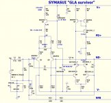
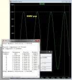
I am now "proofing" my "symasui" ... I actually am
designing this for my subwoofer. I am quite sure it is
musical for HF , as well (33ppm 20k 120v p-p).
The "proof" is how NAF/Thimios get to hear it sing FIRST TIME.
NO smoke or oscillation ...
(below 1-2)
-Blue = V-
-RED = V+
-Green= ground
-yellow= AC (NFB/input signal)
-Pink=inverting signal path
-Purple=non-inverting signal path
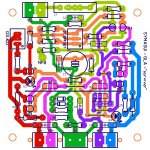
After I do the fancy colors , the "flow" of the amp/layout becomes
apparent , as does any "no-no's" ... like a long parallel set of traces
near C6 (5pF) , as a general example. 🙂
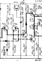
One more explanation of this topology ...
In it's simplest form ... the sansui Z3900 (below 3) , 3 transistors for VAS
(Q5) .. is the level shifter , Q6/7 form the push pull.
A very simple single ended symmetric amp. THD = .05% (500 ppm)
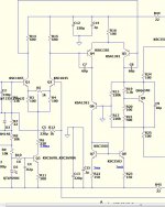
DIYA's "symasym" is a vast improvement (below 4) ,Q4/6/7 form
the level shifter with Q8/5 forming the output. Still,... Q5/8 are doing
ALL the I/V conversion of the VAS .... THD 100-200ppm.
Then there is "symasui" .... V and I are separated.
Q4/5 + Q9/10 just handle "I" while the cascode (Q7/8) combines
with Q6 to generate all the voltage swing.
Same theory as the Hawksford without the feedback.
Blows the symasym away .... especially at huge output swings.
THD= 30-50ppm at "ungodly levels".
All 3 work the same way , but the last 2 are incrementally more refined.
The last one "works the least" to produce those huge waveforms.
OS
I am now "proofing" my "symasui" ... I actually am
designing this for my subwoofer. I am quite sure it is
musical for HF , as well (33ppm 20k 120v p-p).
The "proof" is how NAF/Thimios get to hear it sing FIRST TIME.
NO smoke or oscillation ...
(below 1-2)
-Blue = V-
-RED = V+
-Green= ground
-yellow= AC (NFB/input signal)
-Pink=inverting signal path
-Purple=non-inverting signal path
After I do the fancy colors , the "flow" of the amp/layout becomes
apparent , as does any "no-no's" ... like a long parallel set of traces
near C6 (5pF) , as a general example. 🙂
One more explanation of this topology ...
In it's simplest form ... the sansui Z3900 (below 3) , 3 transistors for VAS
(Q5) .. is the level shifter , Q6/7 form the push pull.
A very simple single ended symmetric amp. THD = .05% (500 ppm)
DIYA's "symasym" is a vast improvement (below 4) ,Q4/6/7 form
the level shifter with Q8/5 forming the output. Still,... Q5/8 are doing
ALL the I/V conversion of the VAS .... THD 100-200ppm.
Then there is "symasui" .... V and I are separated.
Q4/5 + Q9/10 just handle "I" while the cascode (Q7/8) combines
with Q6 to generate all the voltage swing.
Same theory as the Hawksford without the feedback.
Blows the symasym away .... especially at huge output swings.
THD= 30-50ppm at "ungodly levels".
All 3 work the same way , but the last 2 are incrementally more refined.
The last one "works the least" to produce those huge waveforms.
OS
Attachments
OS,
Are the Sprint files for the final OPSs here somewhere? The first post references posts with the art as BMP files only. If it hasn't been posted elsewhere yet, could you put up a zip of all the Sprint LAY files for things that are in a 'finished' state?
EDIT: I didn't realize I could 'browse' a threads attachments without a ton of effort. I think I'm finding what I'm after. My Apologies for the bother.
Last edited:
OK, found the 2P and 5P OPS files, but not the 3P. Could you put that one up for us too, please? I'm looking for the Sprint file...
Symasui? I mainly want the output boards to start with, and yes through hole barrels since the outputs mount from the bottom.Do you want a specific one first? For the more significant pads I think we should consider plated through holes, or PTH for all for that matter. Opinions?
OS,
Are the Sprint files for the final OPSs here somewhere? The first post references posts with the art as BMP files only. If it hasn't been posted elsewhere yet, could you put up a zip of all the Sprint LAY files for things that are in a 'finished' state?
EDIT: I didn't realize I could 'browse' a threads attachments without a ton of effort. I think I'm finding what I'm after. My Apologies for the bother.
Just make sure any sprint is V1.2. Except for the spooky and this one (sym) ..
they are still at V1.1 (sure bets ... but untested).
OS
When looking at the thread's attachments I can't see the date posted. They end up sorted alphabetically with no way to tell when something was posted. It is getting harder to find things 🙁.
If I PM you with an email would you be so kind as to email the most current Sprint files to me directly? I would really appreciate that if you can spare the time to do so.
If I PM you with an email would you be so kind as to email the most current Sprint files to me directly? I would really appreciate that if you can spare the time to do so.
still4given,
Let me know what you decide to do, I am only as far away as LA and if it is someplace local that you will get the boards from let me know,
Thanks,
Steven
Let me know what you decide to do, I am only as far away as LA and if it is someplace local that you will get the boards from let me know,
Thanks,
Steven
Hey neighbor, 😀
It will probably be from China and will take a month to get. I'll be happy to buy extras if your interested.
It will probably be from China and will take a month to get. I'll be happy to buy extras if your interested.
still4given,
I am interested. A pair of ouput sections would be fine for now. I don't know which input section you are interested in but I have been looking at the NAD for that. The SymaSui may be another to look at once it is finalized and tested.
Steven
I am interested. A pair of ouput sections would be fine for now. I don't know which input section you are interested in but I have been looking at the NAD for that. The SymaSui may be another to look at once it is finalized and tested.
Steven
Sounds good. I am mainly interested in getting some output boards made. I figured I could maybe etch the small boards. I'll probably build them all before I'm done. 😀 If Jason can get gerbers done for all of them, there are some PCB manufacturers that do small boards more quickly. The last one I used did some pretty large boards for a good price.
Blessings, Terry
Blessings, Terry
OS, with the output boards, are you planning to redesign them to include the MOSFET rail switches (and potentially also the detection circuitry also) that was discussed a few pages ago?
Even if the detection circuit is on a separate daughterboard, wouldn't you want the rail switches on the OPS PCB to minimise wiring.
Even if the detection circuit is on a separate daughterboard, wouldn't you want the rail switches on the OPS PCB to minimise wiring.
OS, with the output boards, are you planning to redesign them to include the MOSFET rail switches (and potentially also the detection circuitry also) that was discussed a few pages ago?
Even if the detection circuit is on a separate daughterboard, wouldn't you want the rail switches on the OPS PCB to minimize wiring.
Nope .. I would put them on the PS boards.
Why mess with a good thing ? ... the OPS's are golden. They work
for the builders , on the simulations , and in my 21 YO HK.
OS
still4given,
Sounds like something my wife would have said, the output boards sound good for a start. Let me know how you want to proceed on that front. I don't think I want to get into making boards myself, I know I could do it but I need to many things to get into that.
Steven
Sounds like something my wife would have said, the output boards sound good for a start. Let me know how you want to proceed on that front. I don't think I want to get into making boards myself, I know I could do it but I need to many things to get into that.
Steven
Slow progress...
Two babies etched, drilled ad tinned.
Now I need to make a decision which IPS to choose.
J

Two babies etched, drilled ad tinned.
Now I need to make a decision which IPS to choose.
J
Any chance of getting the gerber files for at least the output boards? I haven't had much success at etching my own and board houses are getting very inexpensive. I would love to have a few of those output boards made so I can play along. Please, please please. 😀
Blessings, Terry
There will be a groupsbuy very soon🙂
- Home
- Amplifiers
- Solid State
- Slewmaster - CFA vs. VFA "Rumble"