Terry use my link.If you want I can send you Gerbers of one layer
The pads are plated trough this way you can mount the output transistors first before soldering them on the component side
The pads are plated trough this way you can mount the output transistors first before soldering them on the component side
Last edited:
Hi Patrick,
Not sure if I understand you. Do the Gerbers you sent me have solder pads top and bottom with barrels? That is what I would prefer.
Thanks, Terry
Not sure if I understand you. Do the Gerbers you sent me have solder pads top and bottom with barrels? That is what I would prefer.
Thanks, Terry
What do you mean with barrels?
You can solder the output trannies on the bottom copper side and the solder will flow when you heat long enough to the upper pad cause they're plated trough or like I prefer to do solder them on the top side..
You can solder the output trannies on the bottom copper side and the solder will flow when you heat long enough to the upper pad cause they're plated trough or like I prefer to do solder them on the top side..
Sorry, barrels was my way of saying through hole plating.
I'm not sure now if I want to get 5 pair or 3 pair boards made. I'm thinking with 5 pair boards you can use anywhere from 1 pair to 5. Only draw back is real estate on the heatsink.
Thanks, Terry
I'm not sure now if I want to get 5 pair or 3 pair boards made. I'm thinking with 5 pair boards you can use anywhere from 1 pair to 5. Only draw back is real estate on the heatsink.
Thanks, Terry
Same here on the five pairs, that is why I asked earlier if there was an optimum position to place the output devices if we used less than all five. Make the five pairs boards and if we decide later we don't need as many we can get a shorter version or perhaps OS could design a board that you could cut out a section and use jumper wires to put the two ends back together. A few holes with widened circuit paths could allow you to cut the board length and still have the same circuit intact I think?
Or always use the 3 pair boards because they are space efficient ...
Loaded with OnSemi devices for medium power amps (space efficient) or 'double die' Semelab parts (equates to 6 pair onSemi) for high power amps.
Loaded with OnSemi devices for medium power amps (space efficient) or 'double die' Semelab parts (equates to 6 pair onSemi) for high power amps.
Carl,
Could you tell more about the double die Semlab devices? How are they at heat dissipation and are there any drawbacks to using them over five individual pairs?
Thanks,
Steven
Could you tell more about the double die Semlab devices? How are they at heat dissipation and are there any drawbacks to using them over five individual pairs?
Thanks,
Steven
Carl,
Could you tell more about the double die Semlab devices? How are they at heat dissipation and are there any drawbacks to using them over five individual pairs?
Thanks,
Steven
I have no first hand experience using the Semelab parts. I've always used good'ol OnSemi parts. However those that have used the Semelab parts give them good reviews. I suspect Ostripper would be the best resource on that question.
There are two types of these Semetech output "beasts" available.
First , the 6330-R/9410-R.
They come through a little more powerful than a MJL21193/4 pair
with a much higher Ft (60mhz).
With these , you would have a faster (On semi)4-pair equivalent OP
stage. Current capability at high rails would also be better (SOA - 60V+).
Easy to find these ... 4USD$ each - hundreds in stock !
PS - 3 pair of these would be awful close to 5 pair of NJW0302/0281 ! 😱
Then you have the REAL dual die 😱... the 6332/9412 (to-264) -400w !!
Try a 10 pair NJW OP stage !!!! (equivalent)
They are 8.15 - 8.50USD each.
They are harder to find ... most US distributers just have 5-10 in stock.
Oh ! BTW - ya' all use my Gerbers ... I want a "piece" (Boards ++). 😀
OS

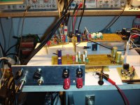
SlewMaster and his brother in progress!
😎😎
Lookin' good ... T
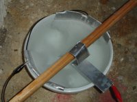
You know you could use just thin common roof/masonry flashing (.39-.45mm) ,
either copper or aluminum as both the OPS driver or IPS VAS heatsinks.
This material can be cut with small shears or even simple scissors !!
On the IPS's , I designed so the thinner material can fit right to the
PCB and almost go from side to side.
It's just the exposed area of the HS surface (CM/2) that counts ,
not the thickness.
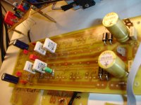
PS- .68u on the Hawksford (IPS board) can be a very low voltage (smaller) , than
those huge wima's you have there ... more room for the green led's !
OS
Last edited:
" PS- .68u on the Hawksford (IPS board) can be a very low voltage (smaller) , than
those huge wima's you have there ... more room for the green led's !"
OS
Thanks SO you don't like these non vertical green leds.🙂
These WIMA cap. are 0.47nF/63V ,at this time i have these only.
BTW i'm on the road for aluminium anodizing for these small heatsinks.
those huge wima's you have there ... more room for the green led's !"
OS
Thanks SO you don't like these non vertical green leds.🙂
These WIMA cap. are 0.47nF/63V ,at this time i have these only.
BTW i'm on the road for aluminium anodizing for these small heatsinks.
Attachments
Last edited:
OS whats your opinion about using squares leds in thermal contact with current sources?
Time past and i can't edit post #1073....these wima capacitors are .47uf(470nf) sorry for this.
Time past and i can't edit post #1073....these wima capacitors are .47uf(470nf) sorry for this.
Last edited:
Spooky and symasui are VERY similar in how they behave at
the "ungodly level" ...
(below ) ... is just 20ppm at over 160V p-p /3R for the spooky.
One needs to go, (40Khz 200v p-p) for the spook to hit .005% ...
The SYM almost does this with 10 devices versus 14 for the
"spook".
These all use the RED LED CCS's - I chose these for 3 reasons ...
-slight negative co-efficient , no need to couple (led/bjt)
-having a cap multiplier on the OPS offsets less PSRR.
-they are super simple/reliable.
PS - I also have the original leach and symasym simulations. They
DO NOT even come close to the (spooky/symasui pair) .. 😱
Edit - these really "fly" because of their VAS's , the Hawksford and wilson/cascoded
VAS retain linearity at a VERY high voltage swing. I have concluded this is why my
listening impression of them at (ungodly) levels ... is "godly" (very,very good).
OS
Attachments
Last edited:
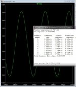
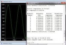
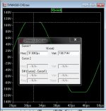
Spooky vs. Symasui ... battle of the "ungodly" VFA's ..
Went a little further and checked clipping , SW . and THD20
at 3R / 200V+ p-p.
Way ahead of any of the CFA's ,the Sym stays double digit PPM
up until about 180V p-p. Goes to .02 -.03% over 200v (below 1).
Clips beautiful at 216V p-p (below 2).
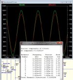
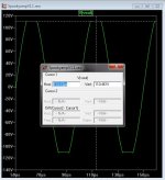
The "TOP DAWG" is still the spook' , it can still have 45ppm/3R
at 200+ V p-p (below 3). It clips out at 220V p-p (below 4).
This is for real .. boys ! The 5 pair with 85V rails @ 4R or 100V
rails for 8R plus some of those Semetech's will give KILOWATT
peaks with these amps.
These 2 VAS's don't even break a sweat doing it , as well.
Current feedback is nice , but it does not scale as well ... both
the CFA-X and NAD nearly reach 600+ ppm at these levels
The "current on demand" and the overly simple single input pair
is not able to stay nearly as linear at these "ungodly" voltage swings.
Yet another VFA superiority (a literal "BIG ONE"). 😱
An "augmented" nad-s with a cascoded second stage could fill in this
performance gap , but it would start to not be as "simple".
PS - even with the superior Hawksford , the NAD's second stage
produces the THD at huge amplitudes - current feedback at it's finest.
At 60V rails and "normal operation" , the CFA's are close to the VFA's.
Not bad for such simple circuits.
OS
Went a little further and checked clipping , SW . and THD20
at 3R / 200V+ p-p.
Way ahead of any of the CFA's ,the Sym stays double digit PPM
up until about 180V p-p. Goes to .02 -.03% over 200v (below 1).
Clips beautiful at 216V p-p (below 2).
The "TOP DAWG" is still the spook' , it can still have 45ppm/3R
at 200+ V p-p (below 3). It clips out at 220V p-p (below 4).
This is for real .. boys ! The 5 pair with 85V rails @ 4R or 100V
rails for 8R plus some of those Semetech's will give KILOWATT
peaks with these amps.
These 2 VAS's don't even break a sweat doing it , as well.
Current feedback is nice , but it does not scale as well ... both
the CFA-X and NAD nearly reach 600+ ppm at these levels
The "current on demand" and the overly simple single input pair
is not able to stay nearly as linear at these "ungodly" voltage swings.
Yet another VFA superiority (a literal "BIG ONE"). 😱
An "augmented" nad-s with a cascoded second stage could fill in this
performance gap , but it would start to not be as "simple".
PS - even with the superior Hawksford , the NAD's second stage
produces the THD at huge amplitudes - current feedback at it's finest.
At 60V rails and "normal operation" , the CFA's are close to the VFA's.
Not bad for such simple circuits.
OS
Attachments
Last edited:
- Home
- Amplifiers
- Solid State
- Slewmaster - CFA vs. VFA "Rumble"