FMBM5551/5401 has considerably high i/p cap as much as 20pf? so no linearity issues? wouldnt the IMD higher with the high pf transistors?
Yes , Cib is 20pF.
But Cob is 6pF. The FMBM5551/5401 are the cascodes , i/p is the 12V zener shunt
regulators.
I'm most likely going to use single BC807/817 smd for the current sources.
Here , the 1.8V led is i/p.
I not only had to make most of my own components (below) , but had to
consider what the most common internal pinout is for low voltage and HV
dual SOT23-6 packages are.
The dual 807/817's are going to be my choice for all differentials (on all
my IPS's). Single 807/817's for the active hawksford semi's and ZXTD4591
"greenie's" - N/P matched for super-pairs.
All these are 3X3 mm bigger SMD. I don't know if the 363 packages will
fit the SOT23-6 pads , but their pinout is the same for both LV/HV.
So - just BCxxx , 5551/5401 , TL071 , and our favorite 1381/3503's .....
all standard cheap (.11 - .49$) parts.
OS
Attachments
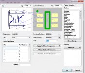
No, different pitch!!All these are 3X3 mm bigger SMD. I don't know if the 363 packages will
fit the SOT23-6 pads , but their pinout is the same for both LV/HV.
From I remember there are duals available in the common SOT23-6, SOT126, SOT-363 pkgs. EIAJ may have a few more too. iirc i think there is even a sot-563.
Might be possible to make a multi-device footprint, I have never done it for these however.
I assume them to mean
PD+, is for positive drive
ND-, is for negative drive
Last edited:
Yes , Cib is 20pF.
But Cob is 6pF. The FMBM5551/5401 are the cascodes , i/p is the 12V zener shunt
regulators.
I'm most likely going to use single BC807/817 smd for the current sources.
Here , the 1.8V led is i/p.
I not only had to make most of my own components (below) , but had to
consider what the most common internal pinout is for low voltage and HV
dual SOT23-6 packages are.
The dual 807/817's are going to be my choice for all differentials (on all
my IPS's). Single 807/817's for the active hawksford semi's and ZXTD4591
"greenie's" - N/P matched for super-pairs.
All these are 3X3 mm bigger SMD. I don't know if the 363 packages will
fit the SOT23-6 pads , but their pinout is the same for both LV/HV.
So - just BCxxx , 5551/5401 , TL071 , and our favorite 1381/3503's .....
all standard cheap (.11 - .49$) parts.
OS
Have you worked with mmbta42/92? Maybe good for VAS stage☺
Have you worked with mmbta42/92? Maybe good for VAS stage☺
Those might be good as a TO-92 and 650mW. Here , if you kept the rails
<60V .... they just might run a 5ma VAS.
The MMBTA42/92 is a paltry 300mW. At >70V rails , even the TO-126
1381/3503's ( 7W) , get warm at over 6mA.
They might be good for input stage cascodes ?? They are real good for
the DC detect on protection circuits and other HV/hard duty circuits.
OS
No, different pitch!!
From I remember there are duals available in the common SOT23-6, SOT126, SOT-363 pkgs. EIAJ may have a few more too. iirc i think there is even a sot-563.
Might be possible to make a multi-device footprint, I have never done it for these however.
I assume them to mean
PD+, is for positive drive
ND-, is for negative drive
ok make sense, I think is a good way to identified them 🙂 I have been reading this thread and is a lot of good information that is for sure

Regards
Juan
Im thinking to use 12aX7 valve at the input instead of bjt or jfet.Those might be good as a TO-92 and 650mW. Here , if you kept the rails
<60V .... they just might run a 5ma VAS.
The MMBTA42/92 is a paltry 300mW. At >70V rails , even the TO-126
1381/3503's ( 7W) , get warm at over 6mA.
They might be good for input stage cascodes ?? They are real good for
the DC detect on protection circuits and other HV/hard duty circuits.
OS
what is your opinion on using valve at the input? Can it give that micro and nano details?
OMG !!
I know you all have seen the forum hybrids. Good for those that have created
them.
A valve has no place in a modern SS amp. Keep it in the pre-amp.
I want an amp that settles in milliseconds and lasts 20 years.
No 6V heater supplies , No valves here. Sorry.
PS - I'm frustrated by diptraces autorouting of the 70+ spooky components.
I could of manually lay'ed out two IPS's in the time I've spent on this CAD !
😡😡
OS
Don't bother with the autorouter. They don't work for audio in any software. They're only useful for a digital circuit, and do a nasty job at that.
hey wait,
autorouters "are" good for one thing ....
a good laugh at what they come up with.
🙂
mlloyd1
autorouters "are" good for one thing ....
a good laugh at what they come up with.
🙂
mlloyd1
so the valve doesn't settle in milliseconds?OMG !!
I know you all have seen the forum hybrids. Good for those that have created
them.
A valve has no place in a modern SS amp. Keep it in the pre-amp.
I want an amp that settles in milliseconds and lasts 20 years.
No 6V heater supplies , No valves here. Sorry.
OS
I have seen one of the member did the valve input in the similar setup but with super pair output.
People who reviewed expressed very nice sweet sound.
But I really have a doubt that can a valve beat the micro details of Jfets?
Attachments
so the valve doesn't settle in milliseconds?
I have seen one of the member did the valve input in the similar setup but with super pair output.
People who reviewed expressed very nice sweet sound.
But I really have a doubt that can a valve beat the micro details of Jfets?
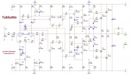
This was the amplifier that brought about the 21st Century Protection system. The tube needs to be warmed up for 30 seconds before the rest of the amp is powered up, otherwise output voltage was pretty wild on start up.
Sprint Layout 6 has that option but results are really ugly xD
Sprint's autorouter would only try to route 1 trace at a time. Diptrace will try to route the whole board from a schematic. If it has a huge area to work with, or 4 layers it does okay, but not good. If the design is compact, it's useless.
so the valve doesn't settle in milliseconds?
I have seen one of the member did the valve input in the similar setup but with super pair output.
People who reviewed expressed very nice sweet sound.
But I really have a doubt that can a valve beat the micro details of Jfets?
You can only build and listen and compare. At this level of performance the difference is very subtle - micro-nuances. This is a very fine amp, but in the end - different people have got different tastes.
This was the amplifier that brought about the 21st Century Protection system. The tube needs to be warmed up for 30 seconds before the rest of the amp is powered up, otherwise output voltage was pretty wild on start up.
I am wishing out loud that the 21st could be integrated into the output board too.😀 SMD and all...😀
I've got tester boards on order that will put the controls right on the speaker binding posts and will connect to OS's on board protection.
I am wishing out loud that the 21st could be integrated into the output board too.😀 SMD and all...😀
We already have some sensors integrated in some OPS boards (temperature, over-current) 😉 DC offset protection circuit looks good together with the output terminals. Processor module is standalone, one per compartment. Looks like a reasonable setup to me.
There's also a light single-PCB version of the control board, combined with the speaker terminals for 2 channels and still having I2C bus plug - performing all the functionality, staying compact and inexpensive - Jeff did a great job making it happen

Huh - just typed at the same time 🙂
Last edited:
A power relay board will still be needed also. I've got a version of that in the works with an integrated control as well for larger dual supply amps.
- Home
- Amplifiers
- Solid State
- Slewmaster - CFA vs. VFA "Rumble"