1. Guys: I know we must be progressive but there is much to be said of keeping our projects in the DIY realm. I am not a manufacturer. I have an junk box full of Dale RN60D, 1% resistors that I have been hoarding as well as several hundred TO-92 transistors and I would like to use them and not re-buy almost microscopic resistors.
2. Also if you go to the trouble of matching SOT transistors, handling them with tweezers between fumble fingers, glueing their flat faces together to control thermal drift in a matched diff amp pair seems to me rather difficult.
3. I guess you could glue a piece of thermal conductive aluminum from SOT to SOT. I will probably only build another one set of amps in my life being now 68 years old, so delving into surface mount at this stage in my life is where I don't want to go. I have the thru hole spooky boards and will live with that. Ray
I'm old too , with slight Parkinson's. Very hard to grip small parts and keep the
"shake" down to solder "fine".
1. I'm keeping any output stage or high wattage resistors passive - all through-hole. As well as bulky electrolytic's.
2. My spooky differential's are going to be FMBM5401/5501 and
BCxxx. These packages are over 3mm , nearly as big as a pair of TO-92's.
A pair of 92's , you have to align the leads through the holes , align height
of the pair and then clip the leads (after soldering).
Not counting you have to match the pair of TO-92's
On my chosen SSOT-6 packages , just a tiny dab of contact cement ...
position on the pads. NO matching or clipping , my pairs are 5% gain
matched on a single die.
As far as input stage resistors , 1206's are easy. Slide it over the pads with toothpick ,
solder one side (then the other). NO bending or clipping.
These resistors can go right between pins or under the semi. The "footprint"
of an input stage made like this can be so small as to not pick up any noise
though winding traces. Same for the caps. IC and small signal decoupling
can be right at the semi ... instead of out on a trace.
Performance... current induced and RF will be nearly eliminated.
3. The through hole spooks are what I have now , My SMD is the same circuit.
What will be better is the trimmable offset for that last couple mv with
an SOIC-8 TL071 , The thermals and matching will be better by the
devices ..... and the PCB will be MUCH smaller.
I'm not replacing the Spook with a computer or anything , just bridging
a gap between the centuries. 😀
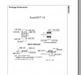
Below - a SSOT-6 .... it's not really too small and contains a matched pair
that uses a different process/wafer (lower Cob and noise).
An SMD op-amp is the same size as a DIP-8.
The resistors are about as big as a 1/8W through-hole.
OS
Attachments
Last edited:
Even Q5,Q6 pair Q7,Q8 pair to be matched or not required?Nope , NFB can take care of that.
Input pairs are more important to have similar beta's.
OS
Attachments
OS: Can I use the new SMD spooky IPS boards with the thru hole output boards I have already bought? I really admire your work. I have an electronic crossover system. I'm building six amplifiers to repace the Leach LTIMs not just one stereo amp. Have you measured the phase angle of the spooky? Thanks, Ray
OS: Can I use the new SMD spooky IPS boards with the thru hole output boards I have already bought? I really admire your work. I have an electronic crossover system. I'm building six amplifiers to repace the Leach LTIMs not just one stereo amp. Have you measured the phase angle of the spooky? Thanks, Ray
That's the plan. I'll be using my new creation on my through-hole OPS's.
Everything is backwards compatible.
Another (cool) reason is to make the IPS SMD (and under 50mm). This
will make the whole OPS/IPS <300mm in total length. All of it will
fit a standard extrusion - flat. NO more wires.
Nope , never tested spooky phase.
OS
OS are you going to use the Toshiba HN1B04fu or the BC847 p/n duals in your designs. If not what are you considering at this juncture? I am wanting to order some from Mouser...
Thanks
Thanks
Last edited:
Thanks for the empathy. I opened a plastic sleeve of smd 8 pin opamps tl071 and they scooted all out the sleeve over the bench and floor. Had to get down on my knees to pick all of them up and back into the plastic sleeve. At least the wire leads are a handle to hold them.Progress! We seem very willing to discard technology. Raygrhughes:
i feel that pain too!
i find that it's perfectly acceptable to use though-hole parts in a "surface mount approach" (i.e. no holes to drill, just cut the device leads and solder to PCB pads).
mlloyd1
Thanks for the empathy. I opened a plastic sleeve of smd 8 pin opamps tl071 and they scooted all out the sleeve over the bench and floor. Had to get down on my knees to pick all of them up and back into the plastic sleeve. At least the wire leads are a handle to hold them.Progress! We seem very willing to discard technology. Ray
There's an upside and a downside to everything. Have you ever stepped on a dip package without shoes on? The SMT version doesn't hurt as much.
There's an upside and a downside to everything. Have you ever stepped on a dip package without shoes on? The SMT version doesn't hurt as much.
ha, ha,
tru dat ...
mlloyd1
😀
There's an upside and a downside to everything. Have you ever stepped on a dip package without shoes on? The SMT version doesn't hurt as much.
50/50 on that one.
Thanks for the empathy. I opened a plastic sleeve of smd 8 pin opamps tl071 and they scooted all out the sleeve over the bench and floor. Had to get down on my knees to pick all of them up and back into the plastic sleeve. At least the wire leads are a handle to hold them.Progress! We seem very willing to discard technology. Ray
You are on the physical end of this "advancement".
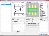
(below) is the library of it.
I now have all the SOT models/libraries - I'm "dangerous" now !!
I know they are smaller , but the SSOT-6 or the infinion SOT457/SC-88 (whatever) are DIY friendly.
The outline I will make to take anything from the 363 to the SSOT (bigger).
So whatever teeny tiny SOT to the big SOT will work with my final layout.
I will also make any single SOT semi universal from the tiny to the
"supersot" 3mm package.
PS - I want to be able to do this , as well. (i am old , too).
Edit - I have to make a component layout that accommodates SSOT -6 /SOT23-6/363 - all at once.
Builders will have a great choice of dual device options.
OS
Attachments
Last edited:
Ostripper can you please let me know about it? do we need to match Q5,Q6 pair Q7,Q8?Even Q5,Q6 pair Q7,Q8 pair to be matched or not required?
Attachments

Ostripper can you please let me know about it? do we need to match Q5,Q6 pair Q7,Q8?
Not critical , but at least get close.
NFB will correct everything .
Even as this is true , the closer you get to optimal ... NFB will not
have to "try as hard" to correct mismatches.
When I make this one a SMD creation , this issue will no longer exist. 😀
PS- I plan on making a dozen SMD IPS's. ALL will work with the
original slewmaster OPS or the new "interleaved" OPS.
The new interleaved OPS will also be modular. With a 45mm mini IPS ,
this IPS will be no larger than a couple of large electrolytic's.
PS - I have fully thought this next "level" out. I guarantee it will be
absolutely SOTA . "category 6 amps"
OS
although I'm not OS, it never hurts and most often helps to match diff pair semis in these kinds of circuits.
mlloyd1
PS - never mind; looks like OS and I were typing at the same time ...
mlloyd1
PS - never mind; looks like OS and I were typing at the same time ...
Ostripper can you please let me know about it? do we need to match Q5,Q6 pair Q7,Q8?
Ostripper can you please let me know about it? do we need to match Q5,Q6 pair Q7,Q8?
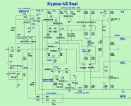
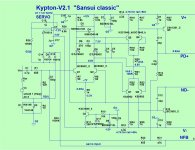
Oh , you might want to look at K-V2.1.
Any layout based on v2 is the same ... just some value changes.
V2.1 is stellar 8ppm max power goodness. Sansui would be proud. 😀
Edit - C3 and 6 are the critical components , 150-270p for 3 and 3.9 - 10p for 6.
the tradeoff is overshoot versus 20k gain margin. ALL the value ranges will
not induce excessive ringing.
Edit 2 - feel free to use your 2Q CCS instead of the v2.1 led one. The first
stage of the K-V is mostly current "blind" . the second stage I is dependent
on the Vf of D5-6.
OS
Attachments
Last edited:
Not critical , but at least get close.
NFB will correct everything .
Even as this is true , the closer you get to optimal ... NFB will not
have to "try as hard" to correct mismatches.
When I make this one a SMD creation , this issue will no longer exist. 😀
PS- I plan on making a dozen SMD IPS's. ALL will work with the
original slewmaster OPS or the new "interleaved" OPS.
The new interleaved OPS will also be modular. With a 45mm mini IPS ,
this IPS will be no larger than a couple of large electrolytic's.
PS - I have fully thought this next "level" out. I guarantee it will be
absolutely SOTA . "category 6 amps"
OS
when you go to SMD version you mean to say that matching will not be an issue in SMD? I actually thought matching would generally be a problem in SMD as they are miniaturized.
What is SOTA Category 6 amps?
when you go to SMD version you mean to say that matching will not be an issue in SMD? I actually thought matching would generally be a problem in SMD as they are miniaturized.
What is SOTA Category 6 amps?
Must you ask ?
Actually , both NPN's (or PNP's) are one chip inside the dual package.
This makes both semi's with the same oxide layers .... they are "deposited"
at the same time. 2-5% is the match between the dual's.
Besides this advantage , SMD will allow plenty of room for a ground
plane and there will be nearly no length of traces between input stage components.
They will have a much smaller area and pick up less hum/RF.
Almost no parasitic capacitance's ... we can build the input stage like a
FM radio receiver.
Edit - I was joking ..."Cat 6" is a quieter , smaller , cooler amp stage.
OS
😀
which dual is as good as 992, 1845 ?
😀
which dual is as good as 992, 1845 ?
Those are the HV ( 120Vce).
I just chose FMBM5551/5401 for those.
Any lower voltage input stage critters are BC857/847 -BS
or Panasonic DMA20402/20403 "critters".
They are better - die is the same for both N/P pairs.
Other specs are similar.
OS
FMBM5551/5401 has considerably high i/p cap as much as 20pf? so no linearity issues? wouldnt the IMD higher with the high pf transistors?Those are the HV ( 120Vce).
I just chose FMBM5551/5401 for those.
Any lower voltage input stage critters are BC857/847 -BS
or Panasonic DMA20402/20403 "critters".
They are better - die is the same for both N/P pairs.
Other specs are similar.
OS
OS: How do we create interest in a group buy of SMD IPS boards and these "matched" dual devices? Also if these input transistors are in cascode then doesn't that increase (double) their collector to emitter breakdown voltage. I'm not an engineer and probably showing my ignorance. Thanks Ray
- Home
- Amplifiers
- Solid State
- Slewmaster - CFA vs. VFA "Rumble"