For home audio "God Save My Speakers at ANY COST" is the amplifier protection design goal, and "clipping = shutdown" is one of the commandments.
The "Ultimate Protection Circuit" compares the output =? input and will shut down the amp if the clipping error is just a few percent.
Give me that Old Time Religion...
Give me that Old Time Religion...
Give me that Old Time Religion...
...
It's good enough for me.
Are you criticizing ?? 😀
This could be easily added to Vzaichenko's 21st century protection.
The spooky Hawksford Cascode LED's forward voltage drops considerably
at even the slightest hint of saturation.
We could just monitor this voltage and set a trip point. With a micro
monitoring this , you could script the protection to mute 10db ... or
shut off the SS relays. Or any other thing you wanted.
Monitoring the "heart" of the IPS for saturation is the easiest way
to detect clipping. The Slew IPS's will always clip at 3-5V below
the rails (cap multipiers and cascode V drops).
OS
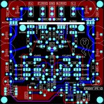
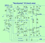
This is my layout for Spooky V2. I'm planning to built it.
You are using the super-pair mod.
You know , the spooky runs just the same on -
- the hawksford (original)
- the super pair
- or the "symetri" VAS.
Hey , look below ... this is my spooky and note how it is grounded.
OS
Attachments
OS: How well matched are those super-pairs you're talking about using in your upgraded SPOOKY IPS and OPS? Ray
NICE LAYOUT!Are you using a ground plane foil side like Prof Leach? Some people say that those boards without the ground plane sound better. Ray
OS: How well matched are those super-pairs you're talking about using in your upgraded SPOOKY IPS and OPS? Ray
If you think the through-hole is good wait till I get this SMD-diptrace down.
(below 1).
I'm choosing packages that you will still be able to pick up with your fingers. 🙂
I've made my choices -
For SMD - 1210/1206/SOT-23-6/3 SOIC-8 for the servo.
-All semi's except for the TO-126 3503/1381 VAS pair and the 1W zeners.
-All resistors except the Zener shunts.
-All diodes and LED's.
Trimmers , 1W zener circuit , VAS and electrolytic's will still be through-hole.
The servo will be a TL071 with it's added offset trimmer. You will be able
to zero that last 1-2mv offset within the servo.
The PCB will accept either the 2 transistors for the Hawksford or the 4 for the
super-pair mod's.
Super pairs / cascodes / input pairs will be matched dual smd devices.
Matching is <5% in the dual packages.
These spooky's also run with less current ..... the single op-amp + lower CCS
current's.
In fact , the slew OPS will support 4ma VAS I - these will run "ICE cold"!
The Cascode = choice of either blue or red reference leds. 2 reds will just
add slightly more negative co-efficient to the VAS I. I've tried both and still
stay within +/- .1ma .
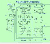
Below 2/3 are the 2 schema's I am integrating into Diptrace. I had to make
the component #'s the same for both mod's.
Size = 40mm X 75mm. Smaller than a portable MP3 player .
Edit - Oh - grounding . I'm going to pour a plane under the LTP/Cascode/CCS's , star it to the decoupling
returns at the interface (like my through-hole version).
OS
Attachments
Another little trick to make soldering easy is to install 805 passives on a 1206 footprint. It gives you a little more room for the soldering iron to heat the trace.
PMLL4148L are easier to solder too.
PMLL4148L are easier to solder too.
Last edited:
Hi , Jeff !Another little trick to make soldering easy is to install 805 passives on a 1206 footprint. It gives you a little more room for the soldering iron to heat the trace.
PMLL4148L are easier to solder too.
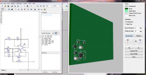
Diptrace did not have the 3296y trimmer 3D WRL. Where do you get
missing 3D images ?
I would also like any 3d+libraries for plug-in or standard euro connects.
I'm "launched now". These will be done.
OS
I haven't found a 3D model for the terminal blocks. It has a model for the standard Bourns 3299w trimmers. That will give you a rough idea for spacing. There are some more 3D models available if you search the Diptrace forums. I've never bothered to add any to mine.
Any of these modular IPS's that I do with Diptrace will be compact < 45 X 75mm.
With this "footprint" for the IPS , Diptrace seems to support the import of
a smaller layout to "drop" into a larger layout (OPS).
With a much smaller IPS , I might even have the option of keeping a modular
design. With a new OPS , I also might consider a smaller connector.
I have V2.402. I see the current 2.2Gb 3D models and comp/ pattern files
(at the diptrace site) , are way larger than what I currently have.
I may "luck out" here !
OS
Any of these modular IPS's that I do with Diptrace will be compact < 45 X 75mm.
With this "footprint" for the IPS , Diptrace seems to support the import of
a smaller layout to "drop" into a larger layout (OPS).
With a much smaller IPS , I might even have the option of keeping a modular
design. With a new OPS , I also might consider a smaller connector.
I have V2.402. I see the current 2.2Gb 3D models and comp/ pattern files
(at the diptrace site) , are way larger than what I currently have.
I may "luck out" here !
OS
3.001 is the latest.
But you can download the 3d's/library's separate. They all work with V2.4+.
Version history 2.4 ---->3.0 is just a bunch of obscure tweaks unnecessary to
make good amps!
What did change was the thousands of extra components (what I'm after) 😀.
"ain't broke , don't fix it" (unnecessary upgrades/updates)
OS
Version history 2.4 ---->3.0 is just a bunch of obscure tweaks unnecessary to
make good amps!
What did change was the thousands of extra components (what I'm after) 😀.
"ain't broke , don't fix it" (unnecessary upgrades/updates)
OS
Why you bring ltp current from 2.8mA to 3.8mA on new SPOOKY IPS? I think it is little on high side?
LTP current is not "set in stone"
Read the Fairchild "BC560C" datasheet.
Fig 1 - "normalized DC current gain"
The BC reaches 90% at >1.5ma
And , Fig 5 - "base spreading resistance".
Near 2ma is where the noise is lowest ,slew and gain is highest.
You can run the spook LTP devices 1ma with a higher cascode resistance -
(1.2 -1.5K). Cooler amp .... but lower slew , higher noise , and less resistance
to ambient thermal changes.
Or , more current if you adjust the LTP cascode collector R (680-820R)
The average 1.7ma (small) semi operating currents in all my IPS's seem
to be the best compromise. Some devices might benefit from 2ma+ ?
1.5-2ma is the "sweet spot". I've also observed this with a thousand Japanese
designs (2SA/2SC - toshiba/NEC) .
OS
Matching pairs
".......The average 1.7ma (small) semi operating currents in all my IPS's seem
to be the best compromise."
THANKS OS! That's what I wanted to know! I can match with this data. Ray
".......The average 1.7ma (small) semi operating currents in all my IPS's seem
to be the best compromise."
THANKS OS! That's what I wanted to know! I can match with this data. Ray
OS, just so you know - you can pick and choose from that library so you don't have to install the whole 2.2GB including all those parts you may not want.
mlloyd1
mlloyd1
LTP current is not "set in stone"
Read the Fairchild "BC560C" datasheet.
Fig 1 - "normalized DC current gain"
The BC reaches 90% at >1.5ma
And , Fig 5 - "base spreading resistance".
Near 2ma is where the noise is lowest ,slew and gain is highest.
You can run the spook LTP devices 1ma with a higher cascode resistance -
(1.2 -1.5K). Cooler amp .... but lower slew , higher noise , and less resistance
to ambient thermal changes.
Or , more current if you adjust the LTP cascode collector R (680-820R)
The average 1.7ma (small) semi operating currents in all my IPS's seem
to be the best compromise. Some devices might benefit from 2ma+ ?
1.5-2ma is the "sweet spot". I've also observed this with a thousand Japanese
designs (2SA/2SC - toshiba/NEC) .
OS
I think it is Onsemi Bc550C datasheet not Fairchild. Your informations does open my eyes. Thank you!
spooky
Os do you have time to see my pm to you Regarding questions to spooky V2?
Else Thanks again for all the great work☺
Os do you have time to see my pm to you Regarding questions to spooky V2?
Else Thanks again for all the great work☺
LTP current is not "set in stone"
Read the Fairchild "BC560C" datasheet.
Fig 1 - "normalized DC current gain"
The BC reaches 90% at >1.5ma
And , Fig 5 - "base spreading resistance".
Near 2ma is where the noise is lowest ,slew and gain is highest.
You can run the spook LTP devices 1ma with a higher cascode resistance -
(1.2 -1.5K). Cooler amp .... but lower slew , higher noise , and less resistance
to ambient thermal changes.
Or , more current if you adjust the LTP cascode collector R (680-820R)
The average 1.7ma (small) semi operating currents in all my IPS's seem
to be the best compromise. Some devices might benefit from 2ma+ ?
1.5-2ma is the "sweet spot". I've also observed this with a thousand Japanese
designs (2SA/2SC - toshiba/NEC) .
OS
How did you find that(in bold letters), The noise is lower at lower current, the gain of this bjt is highest at about 10 mA and slew rate depends of other things not only current. By the way Fairchild is inferior to ONSEMI, lower ft, higher noise and Cob.
How did you find that(in bold letters), The noise is lower at lower current, the gain of this bjt is highest at about 10 mA and slew rate depends of other things not only current. By the way Fairchild is inferior to ONSEMI, lower ft, higher noise and Cob.
2 things, Dadod .
We not only have noise , but the other 3 factors to consider.
I only made my statement after correlating all 4 factors and observing my
many simulations of classic amplifiers.
Google "noise in semiconductors" ... 7 different noises.
1/f noise is governed by Ib ,,, which is governed by semi gain.Google "noise in semiconductors" ... 7 different noises.
Shot noise by Ic.
So , in a given circuit ... even different grades of a given device would
have different noise characteristics.
Then , Different Ic/Ib/Hfe combo's will affect "flicker noise corner frequency".
Yes , I is not the only slew factor (collector Z ) .... but we have to compromise
ALL these conditions.
I highly doubt that all those Japanese designers were wrong.
OS
- Home
- Amplifiers
- Solid State
- Slewmaster - CFA vs. VFA "Rumble"