I think they are V3.
For 5p mt-200 Is there anything to gain from using mt200 drivers, or is 0302/0281 sufficient for drivers?
Yes, they are the new ... new !!! V3. Wish I had those ... so RED.
Yes , as well. Either MT-100 sankens or the 0302/0281's for drivers
1381/3503 pre's and the MT-200's X 5.
You will be able to run those Ultimax 2R in series (4R) , 800VA -80V
will be >500W. Don't break the china !!!
OS

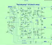
Is this Spooky V2 the latest schematic? I thinking about build it.
I also think the VAS current and led is not valid. It will be 5.4ma for VAS and 2.1->2.5 for led. Is it correct?
I also seen a version of Spooky that have the dc servo opamp ground (2x914 + 1u + 1000k) go to G2(l) instead of G2 like this schematic. Which one is correct?
Why R20 + R20 must be 1/2W ?
I also think the VAS current and led is not valid. It will be 5.4ma for VAS and 2.1->2.5 for led. Is it correct?
I also seen a version of Spooky that have the dc servo opamp ground (2x914 + 1u + 1000k) go to G2(l) instead of G2 like this schematic. Which one is correct?
Why R20 + R20 must be 1/2W ?
Attachments
I would actually prefer the output version but I have a doubt that when you have used the parallel diodes across the collectors of LTP would that tamper the low level signals also before clipping?I will , but not any worse than what anti-parallel diodes would do across the
LTP collectors.
(below) T13 or 14 saturate , forward bias T25 .... causing T26 to conduct turning
the LED on.
Short of clipping , the reverse leakage of t25 might affect the LTP.
I've noticed on lower Z circuits like this or the Kypton V .... no issue.
On a higher Z current mirrored input section , reverse leakage is a
bigger issue (like a "blameless").
Here is better one - Clip Indicator (LED) for any power amp
Runs right off the output (real low Z).
Another - Project 146
Clipping Indicator For Audio Amplifiers Circuit Diagram
These all assume you KNOW at what point your amp clips and references
the actual output waveform to a rail. At least this does not require input
stage "meddling". 😀
OS
obscurus,
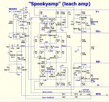
This is the schematic I followed.
How do you think about your spooky?
I would actually prefer the output version but I have a doubt that when you have used the parallel diodes across the collectors of LTP would that tamper the low level signals also before clipping?
Collector Z vs. the reverse leakage of the diodes , that's all. Simulator shows
not a single ppm with or without the diodes.
The reverse clamp diode on either the Badger or wolverine will shave 3-5ppm
at clipping. Much higher Z here.
OS
kapton insulators suck.
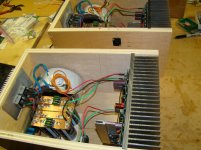
Had my right spooky channel go up in smoke.
One red LED for the 12V on the Spooky IPS was out.
1-10A fuse was blown. Replaced the fuse , magic smoke from one of the
NJW3281's.
Pulled the OPS , a 2mm round hole through one of the Kapton insulators.
The pulled 3281 tested good. So , it was just the insulator.
The extrusion underneath also had a hole from the vaporized Kapton .... 😡
NO burrs or micro dust from metal - just material failure.
Oh well , 15 months+ .... ordered some real mineral mica insulators to go
all around. My Kapton days are through - 5% better thermals are not worth
shortening my 20 years MTBF !!!
OS
Another good reason to stick with Sankens and mica!😀Had my right spooky channel go up in smoke.
One red LED for the 12V on the Spooky IPS was out.
1-10A fuse was blown. Replaced the fuse , magic smoke from one of the
NJW3281's.
Pulled the OPS , a 2mm round hole through one of the Kapton insulators.
The pulled 3281 tested good. So , it was just the insulator.
The extrusion underneath also had a hole from the vaporized Kapton .... 😡
NO burrs or micro dust from metal - just material failure.
Oh well , 15 months+ .... ordered some real mineral mica insulators to go
all around. My Kapton days are through - 5% better thermals are not worth
shortening my 20 years MTBF !!!
OS
At least the mica. NEVER saw a mineral (or a insulator) be the actual cause
of the failure.
Cool that the rest of the amp (and the protection) works perfectly now.
"21st century" tripped on the pad short and the intermittent DC.
Without one rail , the slew OPS does not "slam" the other rail , sort of floats around +/- 2V ... that's it.
OS
of the failure.
Cool that the rest of the amp (and the protection) works perfectly now.
"21st century" tripped on the pad short and the intermittent DC.
Without one rail , the slew OPS does not "slam" the other rail , sort of floats around +/- 2V ... that's it.
OS
I found it important not to torque down on it when using Kapton film as insulator. I had a similar failure with a torqued-down transistor. The mounting hole in the heat sink was drilled with a hand-held power drill then tapped, perhaps not exactly upright. despite the use of a large washer to even out the mounting pressure there could still be some pressure points. I have since given up torquing on the transistors, and instead switched to this spring clip, MAXCLIP, and never needed to worry about over-tightening.
Was just thinking to use soft clipping circuit. How about using this one? What are the pros and cons of using such circuit.
Soft Clipping
Soft Clipping
But that is already in most of my IPS's.
They already "soft clip".
At least all the symmetric ones.
Hawksfords do , with minimal saturation. The super-pair's give both
soft clipping and almost no saturation.
Why "kick the can down the road" ... mitigate the problem from
the beginning.
OS
They already "soft clip".
At least all the symmetric ones.
Hawksfords do , with minimal saturation. The super-pair's give both
soft clipping and almost no saturation.
Why "kick the can down the road" ... mitigate the problem from
the beginning.
OS
But that is already in most of my IPS's.
They already "soft clip".
At least all the symmetric ones.
Hawksfords do , with minimal saturation. The super-pair's give both
soft clipping and almost no saturation.
Why "kick the can down the road" ... mitigate the problem from
the beginning.
OS
Kypton V2 has got soft clipping? the two diodes at the LTP connected in opposite direction above the LEDs does the soft clip?
If by "softer" we mean .... less higher order harmonics and lowerKypton V2 has got soft clipping? the two diodes at the LTP connected in opposite direction above the LEDs does the soft clip?
saturation of proceeding stages. Then yes.
That would describe the V2.
The Kypton C/ND use the super pair VAS. This VAS has even better
rounded clipped outputs. These show almost perfect "soft clipping".
The "Symetri" also exhibits this type output.
The spooky Hawksford also has minimal saturation with overload.
If you consider these as "best". The wolverine/symasui are "inferior".
"Inferior" is just relative , as these two have also been optimized for
minimal saturation. But ... their clip is harder/sharper (with more harmonics).
D. Self (and others) have suggested "just never reach clipping". I know that
an enthusiast will always "push the limits".
PS - the new Groner TIS is another "soft clipper" - same as the super pair.
OS
If by "softer" we mean .... less higher order harmonics and lower
saturation of proceeding stages. Then yes.
That would describe the V2.
The Kypton C/ND use the super pair VAS. This VAS has even better
rounded clipped outputs. These show almost perfect "soft clipping".
The "Symetri" also exhibits this type output.
The spooky Hawksford also has minimal saturation with overload.
If you consider these as "best". The wolverine/symasui are "inferior".
"Inferior" is just relative , as these two have also been optimized for
minimal saturation. But ... their clip is harder/sharper (with more harmonics).
D. Self (and others) have suggested "just never reach clipping". I know that
an enthusiast will always "push the limits".
PS - the new Groner TIS is another "soft clipper" - same as the super pair.
OS
In the earlier replies you have mentioned that using a super pair makes the amp harder to stabilize.
I have few questions Im planning to buy a Martin Logan speaker but to drive with the Kypton V2 so will there be any stability issue since Martin logans are electrostatic speakers so its more capacitive load.
The IPS does not matter , it does not drive the speaker.
The slewmaster OPS "see's" the speaker. I've not heard of any(or had) issues
with this EF3.
The super pair is a mini local feedforward loop within the global loop
of the whole IPS. It (the super pair) "plays well" with lower loop gain
IPS's (CFA's) , or even the spooky front end.
Up at the 120db loop gain of a blameless or Kypton V , problems arise.
The V2 Kypton is just a "plain" 2 device VAS. NO issue.
OS
Was just thinking to use soft clipping circuit. How about using this one? What are the pros and cons of using such circuit.
Soft Clipping
For home audio "God Save My Speakers at ANY COST" is the amplifier protection design goal, and "clipping = shutdown" is one of the commandments.
The "Ultimate Protection Circuit" compares the output =? input and will shut down the amp if the clipping error is just a few percent.
Give me that Old Time Religion...
Give me that Old Time Religion...
Give me that Old Time Religion...
...
It's good enough for me.
- Home
- Amplifiers
- Solid State
- Slewmaster - CFA vs. VFA "Rumble"