Not a all. The typical cuves you can see, breaking a feedback loop is not reflecting what's really happens in closed loop. It is because the phase begin to turn in the VAS & Output stages way before the gain begin to reduce itself. But phase is what matters in a closed loop system, because we compare input signal and feedback signal in the input stage. if the levels are equal and the phases are not equal at 10KHz, in the subraction, you will not have a zero. Right ?I don't think this is derailing, as iam sure the Ostripper an other also would like to understand this new analysis tool,
but why is it that my curve then is flat to app 20KHz, when a Tian probe shows that the gain from the open loop circuit starts to decline from about 1KHz in a typical VFA manner.
Is the tool for CFA only..??
/m
So ,the feedback ratio will not be 100% of what it is at 100Hz.
Is-it more clear ?
I don't think this is derailing, as iam sure the Ostripper an other also would like to understand this new analysis tool,
but why is it that my curve then is flat to app 20KHz, when a Tian probe shows that the gain from the open loop circuit starts to decline from about 1KHz in a typical VFA manner.
Is the tool for CFA only..??
/m
Yes , I would. I have only applied the Tian to measure my ND super-pair
without breaking the loop. Dadod and a few others are way beyond me 😱 .
I'm busy now with hacking ASIO drivers and plugins to push the limits
on the slew's. A better source really makes a difference - the amps are
near perfection.
Oh , I'm all flacs now - NO more mp3's !
OS
Anyone interested in working on Plateau Bias technology?
My amp protection uses all +/- 15V analog fault sense and control logic, and so does this Plateau Bias.
A microprocessor protection methodology would allow a "smarter" bias algorithm.
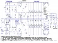
1st attempt at 4-level Plateau Bias Example:
1) Transformer constructed from output inductor senses speaker current and converts into a voltage.
2) From this voltage, 3-comparators are set to detect low, medium, high current demands and drive SR latches.
3) 3-SR latches drive 3-relays which can switch-in 3-parallel Vbe Bias resistors that increase output bias current.
4) Higher bias current demands are immediately provided, and stay plateau until a Reset after 5-minutes detects lower bias needs.
My amp protection uses all +/- 15V analog fault sense and control logic, and so does this Plateau Bias.
A microprocessor protection methodology would allow a "smarter" bias algorithm.
1st attempt at 4-level Plateau Bias Example:
1) Transformer constructed from output inductor senses speaker current and converts into a voltage.
2) From this voltage, 3-comparators are set to detect low, medium, high current demands and drive SR latches.
3) 3-SR latches drive 3-relays which can switch-in 3-parallel Vbe Bias resistors that increase output bias current.
4) Higher bias current demands are immediately provided, and stay plateau until a Reset after 5-minutes detects lower bias needs.
Attachments
Full micro control of the EF3 bias would be a further step.
Quite easy to implement on a high Z OPS .
My 3 pair , lower rail (60V) Sanken OPS stays cool at 50- 200ma
bias.
OS
Quite easy to implement on a high Z OPS .
My 3 pair , lower rail (60V) Sanken OPS stays cool at 50- 200ma
bias.
OS
Has anyone attempted a Kypton ND but balanced version? I have many balanced gears at home and it would be great to be able to use balanced cabling from beginning to end.
Thanks
Do
Thanks
Do
Has anyone attempted a Kypton ND but balanced version? I have many balanced gears at home and it would be great to be able to use balanced cabling from beginning to end.
Thanks
Do
Just a simple op-amp circuit = balanced (below).
OS
Attachments
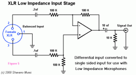
Just a simple op-amp circuit = balanced (below).
OS
Thanks ostripper!
I just somehow hope a Kypton ND PCB could be created using discrete or something like a 1200P08-U?
I'm not really good at PCB layout, actually never attempted...
Do
I might add balanced to the integrated new amp (the one I'm working on).
OS
ooohhhh! Nice!!! Please do! hehehe
Do you have more details on this? 😀
Do
Not that it's a bad thing but in my case I didn't feel that balanced was worth the extra circuitry. I have a pair of jensen jt11p that I use to go from balanced to unbalanced. or to avoid ground loops. http://www.jensen-transformers.com/wp-content/uploads/2014/08/jt-11p-1.pdf
The cfa's are more difficult to give a balanced input than the leach or blameless type circuits as the feedback injection point is very low impedance, and not really symmetric to the input node, we tried to fit a second diamond there, but wedid not manage to make that kind amplifier stable in real life, while it worke really well in simulations
I have the following idea: Build 4x 5P amplifiers, each with their own 400va 35-0-35 v ac transformer (4x). Feed them in pairs with the out of phase signals from the balanced input, bridged into the load. Should work, not?
Opamp = sacrilege
Balanced Line Receivers... It's Complicated.
Opamps can match on-die resistors to 0.1% and match transistors to 1% and match signal path parasitics. Critical for Balanced Line Receivers.
http://sound.westhost.com/articles/balanced-interfaces.pdf
The InGenius® circuit, covered by US Patent 5,568,561, is licensed to THAT Corporation.
http://www.thatcorp.com/datashts/1200data.pdf
Signal-Noise tests show very good results for Jensen transformers.
Attachments

http://www.analog.com/media/en/technical-documentation/data-sheets/SSM2142.pdfBalanced Line Receivers... It's Complicated.
Opamps can match on-die resistors to 0.1% and match transistors to 1% and match signal path parasitics. Critical for Balanced Line Receivers.
http://pdf.datasheetcatalog.com/datasheet/analogdevices/12157751ssm2141.pdf
But never found they sounded fantastic.
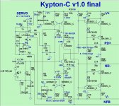
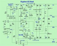
did anybody tried building Kypton V3 up and running well? I had some issues like in the above Kypton V2 circuit.
The D5 dims once you increase the voltage to 12V and we get very odd output voltage from VAS like +2.10V on the positive output and -0.8V for Negative. why is this happening what could be the reason that the D5 led is dimming to almost 50%.
The D5 dims once you increase the voltage to 12V and we get very odd output voltage from VAS like +2.10V on the positive output and -0.8V for Negative. why is this happening what could be the reason that the D5 led is dimming to almost 50%.
- Home
- Amplifiers
- Solid State
- Slewmaster - CFA vs. VFA "Rumble"