What schematic you have used and to what post you found this?did anybody tried building Kypton V3 up and running well? I had some issues like in the above Kypton V2 circuit.
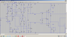
The D5 dims once you increase the voltage to 12V and we get very odd output voltage from VAS like +2.10V on the positive output and -0.8V for Negative. why is this happening what could be the reason that the D5 led is dimming to almost 50%.
Last edited:
What schematic you have used and to what post you found this?
http://www.diyaudio.com/forums/atta...ary-input-stage-n-channel-jfets-kypton-v2.asc
I have removed the DC servo and used the input capacitor please download the ltspice file.
Attachments
What schematic you have used and to what post you found this?
The beta of the transistors in the KSA992 1845 range of 480
but the 1381 beta is 159
3503 beta is 97. Will that beta difference makes the error? what Im getting or any other reason?
Are these beta values of 480 is high? do we need to reduce the resistors values to reduce something or fine?
I don't think that the beta is your problem,i have used 1381E NAD 3503D in many IPS without any problem.The beta of the transistors in the KSA992 1845 range of 480
but the 1381 beta is 159
3503 beta is 97. Will that beta difference makes the error? what Im getting or any other reason?
Are these beta values of 480 is high? do we need to reduce the resistors values to reduce something or fine?
100p for C6 is very high and propably makes poor phase and gain margins.why did you make these changes?
100p for C6 is very high and propably makes poor phase and gain margins.why did you make these changes?
I have changed the source resistors at the input stage just to reduce the johnson noise but reducing the value will create oscillation issues so if we have higher comp caps then it would compensate the input stage reduced resistor value. I think the effect of the capacitors is quite high let me try reducing the value to may be 22pf and see if anything can improve. But Thimios did u make this circuit work properly? did it worked without any issue?
Is that the comp cap being 100pf is the reason for this strange behavior?
Last edited:
If you look at this schematic
http://www.diyaudio.com/forums/atta...g-some-old-ideas-1970s-ips-ops-dc2-sch-01.pdf
observe the D11 and D12 they are on the either side of the LEDs but in the kypton V2 its on the same side does this contributes the dimming of the one of the leds and getting the over idle current in the emitter resistor at the one of the transistors in the Output stage?
I'M CONFUSED A LITTLE.I have changed the source resistors at the input stage just to reduce the johnson noise but reducing the value will create oscillation issues so if we have higher comp caps then it would compensate the input stage reduced resistor value. I think the effect of the capacitors is quite high let me try reducing the value to may be 22pf and see if anything can improve. But Thimios did u make this circuit work properly? did it worked without any issue?
Is that the comp cap being 100pf is the reason for this strange behavior?
Is this a modified schematic or is original by Os ?
Sorry but i ask again,where you get(#post) the schematic?
I'M CONFUSED A LITTLE.
Is this a modified schematic or is original by Os ?
Sorry but i ask again,where you get(#post) the schematic?
http://www.diyaudio.com/forums/soli...omplementary-input-stage-n-channel-jfets.html
If you look at this schematic
diyAudio
observe the D11 and D12 they are on the either side of the LEDs but in the kypton V2 its on the same side does this contributes the dimming of the one of the leds and getting the over idle current in the emitter resistor at the one of the transistors in the Output stage?
Look man.. what exactly are you smoking?? 🙂
You are confusing everybody with different schematics from different threads. The reason for the diodes being different is that it`s a different circuit and the following stage is totally different...
Are your Jfets matched? measure currents on source resistors.. maybe you have a layout error...
Last edited:
I'M CONFUSED A LITTLE.
Is this a modified schematic or is original by Os ?
Sorry but i ask again,where you get(#post) the schematic?
The only thing that I removed is the DC servo.
I got the sch from this link posted by OS
http://www.diyaudio.com/forums/atta...er-cfa-vs-vfa-rumble-002_mosfet_kyptonasc.asc
Last edited:
Im using LSK489 which is a dual jfets.Look man.. what exactly are you smoking?? 🙂
You are confusing everybody with different schematics from different threads. The reason for the diodes being different is that it`s a different circuit and the following stage is totally different...
Are your Jfets matched? measure currents on source resistors.. maybe you have a layout error...
Even tried using 1845 also for the input
its matched accuracy is one beta 485 and another 483
can you do me a favour can you please post the exact version what you have used and any problems you have experienced with these? did u try jfets at the inputs? apart from that what was your betas for the input transistors?
Last edited:
I have built and test the Kypton C, Kypton V and Kypton ND.The only thing that I removed is the DC servo.
I got the sch from this link posted by OS
http://www.diyaudio.com/forums/atta...er-cfa-vs-vfa-rumble-002_mosfet_kyptonasc.asc
I have test the Kypton V with Mat 02 as input trans. I will try to see where this Kypton V 2 is different
The only thing that I removed is the DC servo.
And what did you replace it with ? 🙄
OS
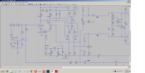
With DC blocking capacitor 2.2uf and 100uf ( C18 ) on the feedback rail.And what did you replace it with ? 🙄
OS
Attachments
Last edited:
Im using LSK489 which is a dual jfets.
Even tried using 1845 also for the input
its matched accuracy is one beta 485 and another 483
can you do me a favour can you please post the exact version what you have used and any problems you have experienced with these? did u try jfets at the inputs? apart from that what was your betas for the input transistors?
I never built any of these circuits, But...
My suggestion to you is:
Disconnect Q5, Q6, Q7 Q8 , pull them completely out, and test the input differential pair by itself and see what happens.
You may have a strong DC offset somewhere, and through the feedback it pushes your input pair to the max in one direction or the other.
So.. disconnect the feedback resistor R31, ground the negative input with 22K, and see where your offset starts at..
Let us know.
Last edited:
There's no real need to disassemble the board yet. It's a symmetrical circuit design. With the input shorted, current flow should be equal in R7 and R8. Also in R18, R19, R22, R23. You have it drawn in LTSpice. Compare current readings through resistors between the two and see where the difference is. That should point you to the issue.
There's no real need to disassemble the board yet. It's a symmetrical circuit design. With the input shorted, current flow should be equal in R7 and R8. Also in R18, R19, R22, R23. You have it drawn in LTSpice. Compare current readings through resistors between the two and see where the difference is. That should point you to the issue.
Look.. with the feedback engaged you will see the results of the DC compensation in places where no actual offset exists...
that`s exactly why one must, at least, disconnect R31 and ground the negative input, in order to get at the heart of the problem.
Last edited:
- Home
- Amplifiers
- Solid State
- Slewmaster - CFA vs. VFA "Rumble"