Os: Could you or someone direct me to the particular post that covers pre-testing the assembled boards and the procedure for adjusting the bias on the spooky IPS with slewmaster OPS boards. There should be a starting value of safe resistance Thanks, GRH
http://www.diyaudio.com/forums/solid-state/248105-slewmaster-cfa-vs-vfa-rumble-847.html#post4457534 Post 8466 and the following couple pages will get you going.
Is there any progress on the Kypton ND test results/ group buy progress. Activity seems to have died down a bit after july/aug.
People have been receiving the Kypton-ND boards for the past week. http://www.diyaudio.com/forums/group-buys/257057-slewmaster-project-boards-70.html#post4491255
can someone post latest schematics of kypton c and kypton v? i want to check for any new parts values that maybe have changed.
This will be my playground.... What will be the sonic effects of letting the OPS run open-loop. 0.05% Distortion from the openloop OPS@54Vpp 20 KHz is no too bad. But what will it mean for the performance. Damping will be a little less and distortion a bit higher the the 1 ppm from the closed loop, but the input circuit no longer have to deal withe what comes back from the speaker and cables... Will be funny..
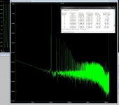
OOHH when you analyse the loop-gain with the Tian probe something funny also pops up.... Gain bandwidth is very different depending on where you that the feedback, this puzzles me a bit. 80dB raw gain to 6-7 KHz on closed loop, and more the 100 KHz @ 50dB on the open-loop version
OOHH when you analyse the loop-gain with the Tian probe something funny also pops up.... Gain bandwidth is very different depending on where you that the feedback, this puzzles me a bit. 80dB raw gain to 6-7 KHz on closed loop, and more the 100 KHz @ 50dB on the open-loop version
Attachments
MiiB, A few other threads on no/limited GLOBAL feedback could be a better info source:
A successful funky feedback amp....Dan d'Agostino MOMENTUM:
Uses Error correction on the outputs, plus separate modest feedback in a loop from input to VAS. This arrangement separates speaker noise and digital network noise on the output wire from the high gain input.
http://www.diyaudio.com/forums/soli...ke-pure-classa-se-despite-low-idle-power.html
Successful no GLOBAL feedback amps...a lot of local feedback is used... Comparing Local vs. Global feedback circuits is worth some study time.
The End Millennium...
Ayre MX-R
Attachments
Though this thread I have been throwing bit and pieces of my work, this has had some effect on the way OS does parts of his circuits,
This open loop idea has two purposes, one is to show that triple EF, may not be the last OPS, the other is to raise some awareness of other ways to take and inject feedback. Which by the way is the starting point of this thread. For some this thread is strictly about building something already designed, for others like me it's more an intellectual exercise, an excursion into circuits and mindsets of skilled audio engineers mindset.
The circuits I"am developing and building are quite different, yet they share the IPS-OPS structure, so the IPS I have posted here, serve as an inspiration for those who know their stuff.
MiiB, A few other threads on no/limited GLOBAL feedback could be a better info source:
A successful funky feedback amp....Dan d'Agostino MOMENTUM:
Uses Error correction on the outputs, plus separate modest feedback in a loop from input to VAS. This arrangement separates speaker noise and digital network noise on the output wire from the high gain input.
http://www.diyaudio.com/forums/soli...ke-pure-classa-se-despite-low-idle-power.html
Successful no GLOBAL feedback amps...a lot of local feedback is used... Comparing Local vs. Global feedback circuits is worth some study time.
The End Millennium...
Ayre MX-R
It is use Bob Cordell's HEC.
I read Edmod Stuart and Bob Cordell debate. Do Bob Cordell's HEC need 0,1% resistor and dificult to trim?
The HEC is also a feedback system, if not carefully applied it may make things worse.
Now I look forward to let the OPS run as a slave of the VAS.
Now I look forward to let the OPS run as a slave of the VAS.
I believe this point needs some clarification. In a normal amplifier (global feedback) you use a lot of open-loop gain, then, apply the most feedback you can.
The input stage just subtract the output signal (after reduction of its level for it matches the input one, minus a percent equal to the open-loop gain of the amp).
In Error correction, you have no voltage gain. But you want a feedback to apply error correction. So, you subtract as precisely as you can the output signal (set at the same level) from the input one, in order to have only the errors between them. Then, you amplify this error signal in phase opposition, as much as you can to correct the distortions. This is more tricky, as there is phase turns at HF that makes errors on the substation and because it need precise gain reduction before comparison. At the end, both are not so different.
In Error correction, you have no voltage gain.
46dB gain in Bob Cordell circuit decreasing over 1KHz to 24dB at 20KHz.
Please, wahab, i know my English is not very good, but try, for once, to understand what I wrote. An output stage has NO voltage gain. (Only current gain).46dB gain in Bob Cordell circuit decreasing over 1KHz to 24dB at 20KHz.
... -> "Then, you amplify this error signal in phase opposition, as much as you can to correct the distortions."
Last edited:
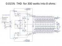
In error correction you use all the circuit gain as feedback and thus end up with a gain of one, I once did something similar, but with a raw gain of 60dB, that circuit did show impressive performance. But one can argue that using that or HEC is not the same as running open loop, or a non global feedback circuit, as you still have loops connecting the input stage to the output. My output stage is non switching and as such there are no nasty crossover flaws that would really need feedback correction, with my circuit there a good distortion profile and it doesn't climb over 0,1% @20KHz even when you approach the maximum rail swing.
Should be very interesting to listen to the difference of ppm distortion and global feedback vs open loop and thus higher distortion and lower damping.
Should be very interesting to listen to the difference of ppm distortion and global feedback vs open loop and thus higher distortion and lower damping.
Please, wahab, i know my English is not very good, but try, for once, to understand what I wrote. An output stage has NO voltage gain. (Only current gain).
... -> "Then, you amplify this error signal in phase opposition, as much as you can to correct the distortions."
There s no voltage gain for the OS as a whole but there s 46dB local NFB provided by the EC between output and input of the OS...
That is exacly what i said. An understanding problem or just the need to contradict?There s no voltage gain for the OS as a whole but there s 46dB local NFB provided by the EC between output and input of the OS...
You agree and yet you fight..🙂 marvelous.
Esperado you never came back to me regarding your gan/feedback ratio curves. Was that because you did not have an answer..? I too think that there's sone understanding we don't fully comprehend.
Esperado you never came back to me regarding your gan/feedback ratio curves. Was that because you did not have an answer..? I too think that there's sone understanding we don't fully comprehend.
Yes, I had seen your answer, but don't know how to explain better. Make an AC measurement at the output of the input stage (the stage where input signal and feedback signal are mixed together). The response curve will be the exact contrary of the feedback ratio one, because at the frequency where the signal begin to increase, it is the frequency the open-loop begin to turn phases. On my opinion, it is useful as no change is made in the closed loop to sim-it.You agree and yet you fight..🙂 marvelous.
Esperado you never came back to me regarding your gan/feedback ratio curves. Was that because you did not have an answer..? I too think that there's some understanding we don't fully comprehend.
In a perfect world, we would like this curve to be flat in all the audio bandwidth.
The other reason why I don't answered was to avoid polluting this thread.
Last edited:
I don't think this is derailing, as iam sure the Ostripper an other also would like to understand this new analysis tool,
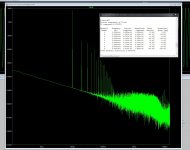
but why is it that my curve then is flat to app 20KHz, when a Tian probe shows that the gain from the open loop circuit starts to decline from about 1KHz in a typical VFA manner.
Is the tool for CFA only..??
/m
but why is it that my curve then is flat to app 20KHz, when a Tian probe shows that the gain from the open loop circuit starts to decline from about 1KHz in a typical VFA manner.
Is the tool for CFA only..??
/m
- Home
- Amplifiers
- Solid State
- Slewmaster - CFA vs. VFA "Rumble"