There will always be some slight mismatch in transistors. With the feedback disconnected, output voltage will head for one of the rails. Any measurement in that state is really useless. Ostripper's inputs are always designed to be very tolerant to mismatched parts, but they need to be complete to operate.
We normally test these inputs standalone with 100R or 1k resistors connecting PD+ and ND- to the feedback input. There is a sim file to compare to. It's easier to see where the live circuit is deviating from the sim first, then figure out what is causing the deviation after. While doing this, any possible layout error usually becomes evident at the same time.
We normally test these inputs standalone with 100R or 1k resistors connecting PD+ and ND- to the feedback input. There is a sim file to compare to. It's easier to see where the live circuit is deviating from the sim first, then figure out what is causing the deviation after. While doing this, any possible layout error usually becomes evident at the same time.
Earlier i did built the only the input stage without the VAS but i didnt ground the negative pin using 22k i forgot but ill do it.Look.. with the feedback engaged you will see the results of the DC compensation in places where no actual offset exists...
that`s exactly why one must, at least, disconnect R31 and ground the negative input, in order to get at the heart of the problem.
In the earlier test the problem was same dimming of the D5 after certain voltage level like beyond 6V.
Ill check now with 22k res grounded.
shall i disconnect everything else to the gate of J2 Jfet and just connect a 22k to ground and check?
shall i disconnect everything else to the gate of J2 Jfet and just connect a 22k to ground and check?
You can even short it to ground..
See, you raise the voltage slowly and test when and where the circuit starts to deviate from center. look first for a major imbalance throughout the stages, ignore the minor ones.
Monitor the output continuously for signs of stress and work your way backwards, stage by stage, from output to input, to see where things start to go wrong.
Last edited:
DIYA allows edit of first post ... ALL current work is posted here !
9. Kypton-C (CFA) - better CFA-X with servo and super-pair. Post # 4729.
10. Kypton -V (VFA) "classic sansui" 3 stage IPS. Post # 5384.
You can even short it to ground..
See, you raise the voltage slowly and test when and where the circuit starts to deviate from center. look first for a major imbalance throughout the stages, ignore the minor ones.
Monitor the output continuously for signs of stress and work your way backwards, stage by stage, from output to input, to see where things start to go wrong.
I have figured out the problem atleast partially.
while drawing the schematic for the pcb design the output transistor for the VAS on positive rail had swapped emitter and collector and now I have swapped it on the pcb and now everything works as expected except one.
I have got LED both versions 1.65V and 1.8V and now in both of the above cases I get all the LEDs glow at same level when driven at 30v where I get 11.74V on the zener for the positive supply and arround 10.1V at the negative supply after the zener diode.
well here is what I got
at ND+ and ND- im getting about 1.17V for ND+ and -1.17 for ND- which I believe is good but thats what Im getting when the bias pots are at maximum.
Now the problem is im getting about 1A of idle current in the emitter resistor of the output transistor which is quite hot and this value is slowly crawling up ( I think its already on its way to thermal runaway ).
This value is not coming down even after having its pots to 1000ohm each.
What could be wrong?
how to debug this.
With resistors installed from PD+ to feedback and ND- to feedback, you should measure 5.5mA on each resistor. This is what the bias spreader is designed to operate with.
Which sch are you referring to?With resistors installed from PD+ to feedback and ND- to feedback, you should measure 5.5mA on each resistor. This is what the bias spreader is designed to operate with.
5.5mA to the bases of a pre-driver in a triple EF sounds a lot !
eg a pre-driver passing 10mA with an hFE of 150 would have a base current of 66.67uA
With resistors installed from PD+ to feedback and ND- to feedback, you should measure 5.5mA on each resistor. This is what the bias spreader is designed to operate with.
so you mean that to connect the PD+ and ND- using an example 100ohm resistor to the point between R31 and R32?
generally what could be the problem? Is the a common error observed?
Install 5w 10 ohm resistors in between the ips and ops in place of the jumper wires at PD and ND. Measure the voltage across each of them. Adjust the ips so you get around 5.5mA.
Which portion of the IPS to be adjusted to get 5.5ma?Install 5w 10 ohm resistors in between the ips and ops in place of the jumper wires at PD and ND. Measure the voltage across each of them. Adjust the ips so you get around 5.5mA.
It looks like R21 is meant to be the adjustment in your schematic.
So that should fix the over bias issue?
I can't say for sure but likely. If VAS current is too high for the bias spreader to be able to adjust, bias current will be high.
Normally we test input boards and output boards separately. The input board will run independently from the output board with resistors installed to the feedback connection. With the resistors connected you should also be able to measure your DC offset at the feedback connection to verify servo operation or offset adjustment.
The output board can be tested independently as well. Resistors can be connected from the positive rail to the PD+ connection and negative rail to the ND- connection to simulate a 5.5mA input current. I usually just use 15k resistors for this and just verify that I have control of the bias circuit before testing with an input, but you can calculate the proper resistors to give you the correct current if you want to be more accurate.
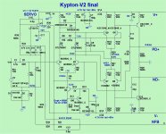
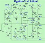
These are the schematics my current builds are based on but as posts moved on i found later schematics with some changes and now i dont know whether to apply the changes or not.More specifically for KYPTON C ,Ostripper posted a schematic where R8 is omitted.For KYPTON V ,Ostripper posted an updated version with a different servo amplementation and many values changed.
Ostripper please elaborate for each schematic.what changes to use?
Attachments
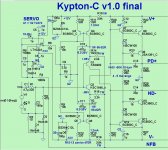
Here's the final Kypton-C schematic. Notice the lower value of R6. The one you have was an error. If I recall correctly, you could remove R8 to give the servo unlimited control of DC offset. With it installed, the servo couldn't drive offset to rail on failure. There are some adjustments to the feedback resistors too.
Attachments
so it means that even beta of the VAS transistors make a difference here? so we must compensate the more current output with increased R21. Let me try that today.I can't say for sure but likely. If VAS current is too high for the bias spreader to be able to adjust, bias current will be high.
Normally we test input boards and output boards separately. The input board will run independently from the output board with resistors installed to the feedback connection. With the resistors connected you should also be able to measure your DC offset at the feedback connection to verify servo operation or offset adjustment.
The output board can be tested independently as well. Resistors can be connected from the positive rail to the PD+ connection and negative rail to the ND- connection to simulate a 5.5mA input current. I usually just use 15k resistors for this and just verify that I have control of the bias circuit before testing with an input, but you can calculate the proper resistors to give you the correct current if you want to be more accurate.
I can't say for sure but likely. If VAS current is too high for the bias spreader to be able to adjust, bias current will be high.
Normally we test input boards and output boards separately. The input board will run independently from the output board with resistors installed to the feedback connection. With the resistors connected you should also be able to measure your DC offset at the feedback connection to verify servo operation or offset adjustment.
The output board can be tested independently as well. Resistors can be connected from the positive rail to the PD+ connection and negative rail to the ND- connection to simulate a 5.5mA input current. I usually just use 15k resistors for this and just verify that I have control of the bias circuit before testing with an input, but you can calculate the proper resistors to give you the correct current if you want to be more accurate.
The mods and the observations:
1. used a 10ohm 5w resistor in series with PD+ and output stage and I got 0 current measured. I indeed checked again and again that if any connection problem and resoldered again but the result is same.
2. changed the resistor R21 from various values and effect is very surprising as follows
a. Increased the value from 62ohm to 100ohm and the bias shootout issue was there
b. Increased to 150 ohm bias again shot out
c. Increased to 820 ohm bias was zero and at psu +/-20V this time but the sound was dynamic and sounded good but i was wrong that there was one more issue which was visible here that at low volumes the sound is completely rough but when I increased the psu voltage to 30V the bias again shootout.
I have checked using dimmerstat what was found is that upto certain voltage the bias is zero and just at that one or two volts up the bias shoots out like crazy. Observations as much as 1Amp per transistor.
d. Increased to 1k the sound was very much the same but the voltage at which the bias was shooting out was gone hence the idle current was 0ma at the emitter resistor.
e. Reduced the 1k resistor at R24 , R25 for negative rail and same resistors for positive rail to 820ohm and now the sound is gone to almost 95% not in gain but in detail I cant even identify which song is being played. so changed the values back to 1k and it again started singing.
But one more thing no matter what the bias was never in between 0 and infinite at any vbe multiplier resistor value.
I thought of running the amplifier in zero bias as it was atleast sounding better than nothing but the distortion at the lower volume is still there.
Measured the voltage values at the R21 and found it was 4.25V exactly as per the sim.
So what would have went wrong....!
I use 100 ohm or 1k resistors to measure VAS current normally. I wouldn't think 10 ohm resistors would cause any issues, but the lower resistance makes it harder to get a good voltage drop reading. With 1k resistor it should drop 5.5 volts.
Unless there is something messed up on the output side, you won't have any bias current in the output devices without VAS current feeding the pre-drivers.
Can you post a schematic of your input? Is this much different than a standard Kypton-V?
Unless there is something messed up on the output side, you won't have any bias current in the output devices without VAS current feeding the pre-drivers.
Can you post a schematic of your input? Is this much different than a standard Kypton-V?
Last edited:
- Home
- Amplifiers
- Solid State
- Slewmaster - CFA vs. VFA "Rumble"