Different speakers may yield different results, but in my experience 25V rails will result in soft bass and poor highs. Higher voltage can dramatically improve the sound.
If you are hearing the amplifier distorting, then the distortion is gross.
You need to find what has been assembled incorrectly.
You need to find what has been assembled incorrectly.
If you are hearing the amplifier distorting, then the distortion is gross.
You need to find what has been assembled incorrectly.
I think its because of the using 4.7k resistors at the power supplies and we are running it at 25V where 4.7k to be used above 50V.
But why is this amp limited to +/-75V? I think it can work even for higher voltages provided the 4.7k to be replaced by a 6.8k or little higher.
why a current mirror not used in this circuit can we use it above the LEDs? any pro and cons specific to this circuit?
I think the rail limit is driven more by the OPS. Are you building a home stereo or a PA system. Do you really need more than 500W/4R? Why are you asking about +-75V when you have chosen to use +-25V? I think that is the lowest rail I have seen used with one of these amps. It certainly wasn't designed with that voltage in mind.
Agreed the fact.I think the rail limit is driven more by the OPS. Are you building a home stereo or a PA system. Do you really need more than 500W/4R? Why are you asking about +-75V when you have chosen to use +-25V? I think that is the lowest rail I have seen used with one of these amps. It certainly wasn't designed with that voltage in mind.
There are few more observations. when i changed the input from 1845 to Jfets the distortion is completely gone but the bass is not as strong as the transistor version. I think its because of saturation charcteristics of 1845 thinking of using bc550. I will try in few weeks as I need to purchase them.
why cant we use a +/-20V with 20v zener at the input stage? wouldn't that be better? the spice sim shows up no issues but anything to consider. The VGS still in limits of the device as low as 11V.
The only change what I made is taking out the servo.Why don't you take a look at the original design. The Kypton-V worked.
Regarding the higher voltage rails for the input stage apart from 12V is that the Vce is being very low as much as 5 to 6V which is quite low agreed that there might be few transistors which can be placed but atleast 10v would make it better I feel.
Can we drain more current through the input mosfet by changing the bottom LED with higher Vref as much as 2.7V? doing so will increase the quiescent current through the source resistors of jfets to 2.6ma per jfet. I would like to increase it more to 7ma per jfet what do you say?
Why don't you take a look at the original design. The Kypton-V worked.
Which is the final version of kypton V? at post #8836 i posted two versions.the first one is the one my build is based on.
Now everything seems working. I still feel couple of places where we can improve the design. can we use a Jfet CSS to feed the input diff pair?Why don't you take a look at the original design. The Kypton-V worked.
planning to use BF862 at the input but as its RF part stabilities might be a problem but we can add the gate resistance to stabilize it so how much should be the gate resistor?
There is one problem using lsk489 in that place as the xconductance is in the order of 1.4mS where as 2sk170 has 22ms which is approx 15 times so can we reduce the source resistors at the input to 2.2ohms instead of 33ohms?
There is one problem using lsk489 in that place as the xconductance is in the order of 1.4mS where as 2sk170 has 22ms which is approx 15 times so can we reduce the source resistors at the input to 2.2ohms instead of 33ohms?
anybody please respond on the resistor change.
What do you think?
Hmmmm... the DC bias looks fine, but how the emitter current of the followers will change?
Sajti
Hmmmm... the DC bias looks fine, but how the emitter current of the followers will change?
Sajti
How single ended VAS current with loaded by constants current source, will change? I forgot the lesson long time ago when I was student.
I think how they work is same 🙂
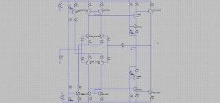
I think I solve the problem of symmetry topology with current mirror. Just add buffer with constant current source, and then VAS quiescent current can determine reliable.
What do you think?
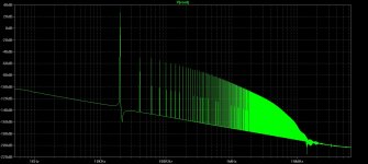
I make a complete simulation of amplifier with this idea. The harmonic profile is interesting. But I need lower THD.
Attachments
How single ended VAS current with loaded by constants current source, will change? I forgot the lesson long time ago when I was student.
I think how they work is same 🙂
Not really. Check the base current of the follower!
Sajti
I think I solve the problem of symmetry topology with current mirror. Just add buffer with constant current source, and then VAS quiescent current can determine reliable.
What do you think?
Hi Bimo, CCS-loaded buffer does not save you from the VAS shoulders' "competition", resulting in common mode balance fluctuation, resulting in the VAS quiescent current fluctuation, unless you arrange a common mode control loop, one way or the other.
See, what I came to last year:
http://www.diyaudio.com/forums/solid-state/248689-xhs-xtra-high-speed-design-5.html#post4098539
I have removed the LTP mirrors and still have got very low distortion. CCS-loaded buffer is also there 😛
Cheers,
Valery
I am in to test one channel of my Slewmaster build. My IPS is the Kypton- ND2. I red the post from post 8480 with interest where “jkuetermann” give “yngvejos” good advices to his setup. “yngvejos” IPS is not the same as mine.
I always use my variable transformer when testing. The max output is +/- 34V DC.
My intention is to test at +/- 30V DC.
“jkuetermann” wrote:” So you need one set of R23/R24 for low voltage testing and a different set of R23/R24 for your intended rail”. What resistors are we talking about on the Kypton-ND2(not R23/R24?), and what value is recommended when the power is +/-30V DC.
I have the same question when it comes to the OPS testing with a “dummy” IPS. What value is recommended to the set of resistors from +V to PD and –V to ND to get the 5mA(about) of current when the supply is still +/-30v DC?
Link to the exact schematic you are building so we can recommend resistor values accurately.
A number of the IPS designs use basic shunt regulation for portions of the circuit. The issue when dealing with large changes in supply voltage is either high dissipation in the resistors feeding the zeners or the zeners dropping out of regulation. This is why one must tailor those values to suit the supply voltages.
Similarly, when testing the OPS independently you need the select resistors based on supply voltage. A simple ohm's law calculation will get you close enough.
SupplyVoltage/TestCurrent=ResistorValue ; Round to closes standard value.
30V/5.5mA=5.45k ; Use either a 5.1k or a 5.6k to get the current close as an example.
You need to adjust R14 and R15 to flow 10-12mA at your selected rail voltage. 30V rails will need 1.5k resistors. You will also need to tailor R18 and R19 to get VAS current correct. There's a lot of info and an updated schematic in the build thread. http://www.diyaudio.com/forums/solid-state/260268-slewmaster-builds-144.html#post4521140
Try around 6.2k resistors for the output board.
Try around 6.2k resistors for the output board.
- Home
- Amplifiers
- Solid State
- Slewmaster - CFA vs. VFA "Rumble"