yes that tip really helped me alot in getting the amp up and running.Link to the exact schematic you are building so we can recommend resistor values accurately.
A number of the IPS designs use basic shunt regulation for portions of the circuit. The issue when dealing with large changes in supply voltage is either high dissipation in the resistors feeding the zeners or the zeners dropping out of regulation. This is why one must tailor those values to suit the supply voltages.
Similarly, when testing the OPS independently you need the select resistors based on supply voltage. A simple ohm's law calculation will get you close enough.
SupplyVoltage/TestCurrent=ResistorValue ; Round to closes standard value.
30V/5.5mA=5.45k ; Use either a 5.1k or a 5.6k to get the current close as an example.
The leds used in Kypton ND-2 are 1.7V types witch I do not have. I do have other types and colors(not important I suppose). This is what I have and all of them are 20mA:
3V
3.2V
3.6V
2.2V
2.3V
Can a pair of one of these be used, or only one alone instead of a pair of 1.7 V??
Where can I find a layout of Jwilhelms Kypton-ND2?
Eivind Stillingen.
3V
3.2V
3.6V
2.2V
2.3V
Can a pair of one of these be used, or only one alone instead of a pair of 1.7 V??
Where can I find a layout of Jwilhelms Kypton-ND2?
Eivind Stillingen.
The leds used in Kypton ND-2 are 1.7V types witch I do not have. I do have other types and colors(not important I suppose). This is what I have and all of them are 20mA:
3V
3.2V
3.6V
2.2V
2.3V
Can a pair of one of these be used, or only one alone instead of a pair of 1.7 V??
Where can I find a layout of Jwilhelms Kypton-ND2?
Eivind Stillingen.
you need those at 1.7V or bias will be very high and goes out of control as I have experienced with this circuit.
Go through the previous thread the link is posted.
Last edited:
The first test of the Kypton ND-2 is done. Test voltage has been +/-30 V DC.
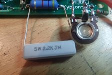
My aim is to use a power voltage of +/- 65 V . So all resistors mounted is taken from the "+/-64V list" exccept for R 18 and R19. As seen from the photo I have made this resistors of a 470 trimpot and a fixed resistor of 510 ohm.. I have monted one blue 3.2V led on each side and shorted "number two". This will be changed to the correct red 1.7 V leds later on. No small heatsink mounted on Q11 and Q12. All this differences might influence on the results. From ND- and PD+ 1K resistors are monted.
With my multimetrs over R22 and R29 I was able to measure approx. 0.66 and 0.68 mV. When I "trimmed" R22 and R29 the results influenced on each other. As a first test of the IPS I hope this shows that it works o.k.?
Where do I check the offset on my IPS?
Eivind Stillingen
Attachments

The offset may not work properly without the OPS attached. A long as you are in the ballpark you should be fine.
I see a giant coupling capacitor...please have a look on this (see at the bottom of page) Capacitor CharacteristicsThe first test of the Kypton ND-2 is done. Test voltage has been +/-30 V DC.
My aim is to use a power voltage of +/- 65 V . So all resistors mounted is taken from the "+/-64V list" exccept for R 18 and R19. As seen from the photo I have made this resistors of a 470 trimpot and a fixed resistor of 510 ohm.. I have monted one blue 3.2V led on each side and shorted "number two". This will be changed to the correct red 1.7 V leds later on. No small heatsink mounted on Q11 and Q12. All this differences might influence on the results. From ND- and PD+ 1K resistors are monted.
With my multimetrs over R22 and R29 I was able to measure approx. 0.66 and 0.68 mV. When I "trimmed" R22 and R29 the results influenced on each other. As a first test of the IPS I hope this shows that it works o.k.?
Where do I check the offset on my IPS?
Eivind Stillingen
Thimios wrote:
"I see a giant coupling capacitor...."
This is a a Audyn MKP QS 4.7uF with 38mm between the legs mounted very close to the PCB. Max distance between the mounting holes are 32mm. Yes I have done some bending to fit. Not recommende?? I took what I have. I have alternatives.
Question: The input are maked pluss + and minus -. Is it ment for singel ended with + as signal and - for ground, or is it for + and minus on a balanced input?
Eivind Stillingen
The input connections are not for balanced input, just audio signal and ground.
The problem with that style of input cap is there are two long unshielded leads and outer foil ready to pick up noise. A radial lead cap like a MKP is preferred.
The problem with that style of input cap is there are two long unshielded leads and outer foil ready to pick up noise. A radial lead cap like a MKP is preferred.
The leds used in Kypton ND-2 are 1.7V types witch I do not have. I do have other types and colors(not important I suppose)
Eivind Stillingen.
the color is most important because the bandgap voltage is directly related to
the photonenergy which is reversely proportional to the wavelength of the light emitted by LED.
Thus red have the lowest and blue the highest ( 1.7V / 3.3V )
the color is most important because the bandgap voltage is directly related to
the photonenergy which is reversely proportional to the wavelength of the light emitted by LED.
Thus red have the lowest and blue the highest ( 1.7V / 3.3V )
There are two pairs of red leds in series meant to drop 3.4V each pair. One blue in place of two red is fine, but the blue is slightly noisier than red.
Another type of fet you can do a ''Fetron'' with two fets for substitute tubes,
use of two fets input G drian to sourse with resistor and upper gate to source of
input fet, you have a higher voltage Fet s.k Fetron,
alcroner
use of two fets input G drian to sourse with resistor and upper gate to source of
input fet, you have a higher voltage Fet s.k Fetron,
alcroner
Help!
Hello fellow forum members!
I am a Hungarian guy, who just bought himself some new ATC SCM11s for his new home studio.
I wish to get the maximum out of those speakers, so I decided I want to build one! The music I will mix on it ranges from classical to electronic music!
I got the information I should ask here what you would recommend me! 🙂
So:
What would you recommend me, If I need at least 150W (those bad boys are not sensitive at all), and I really need high transparency and fast response?
Also:
I have seen the Honey Badger too, but I am unsure which to build, as there are so many options! Is a slewmaster better than the Honey Badger? If yes, what PCBs would I exactly need to achieve the transparent sound, fast transients, and higher power?
Thanks in advance:
Sebastian
The Slewmaster series (Wolverine input in particular)is the big brother to the HoneyBadger. If you want ultimate power to match those speakers I would recommend going higher power. 70V rails with Slewmonster output boards and Kypton-ND input boards will give you around 280W RMS and sound amazing. You would also need protection and softstart boards. http://www.diyaudio.com/forums/soli...-st-century-protection-board.html#post4110406 work well with this. You would need supply boards too.
And how much of which PCB do I need? I am a bit confused:
So the Krypton ND is the IPS, and slewmaster Monster is the OPS? how many of those OPS do I need? just two? What power of toroid transformer I need? 600 VA for 2 channels? Or more?
It seems to me to be a bit confusing, as I don't know what to do, what PSU to build, and what to connect with what 🙂 But I really want to make it, and I am really ready to learn as much as I can to succeed!
Thanks: Sebastian
You need one input and one output board for each channel. The transformer size depends on what you plan to do with the amplifier.
Randy Slone's rule of thumb for transformer sizing is the transformer VA should be double the RMS power output of the amplifier. That would be 560VA per channel. You really don't need anywhere near that large. In my own I use 1000VA, but 600VA total would be more than enough for normal operation.
For least chance of ground loops, mono block designs are superior meaning separate smaller transformers and power supplies for each channel. This can make the amplifier very heavy to move around though. Some are opting to have one channel per chassis for large monoblock designs.
The biggest expense will be the power supply and the chassis. The first thing you should decide is a chassis you would like to use, then see what you can fit into it. Chassis become full very quickly with large amplifiers. After you've selected a chassis, pick a transformer(s) and power supply (or supplies) that will fit into it. The Slewmonster output boards are long, so the chassis needs to be deep and you need to make room for the separate input boards and safety/control boards.
Slones rule of thumb for supplies is you need 10000uF of capacitance per rail for every 100 watts of output, That would be around 60000uf total per channel. In actual use you don't need near that either, but if you are going small on the transformer, go larger on the capacitance to keep bass response.
These amps have excellent PSRR so you don't need anything fancy for a supply. Some use CRC filters, but they aren't really needed. Ostripper designed a supply to go along with these amps. It's pretty simple. Basically 4 diodes and 4 big caps with a couple bleeder resistors.
These amps have excellent PSRR so you don't need anything fancy for a supply. Some use CRC filters, but they aren't really needed. Ostripper designed a supply to go along with these amps. It's pretty simple. Basically 4 diodes and 4 big caps with a couple bleeder resistors.
Last edited:
Can anyone provide me with a working schematic? I got so many questions about the slewmonster too, that which transistor I'll have to use, and things like this. Might aswell copy someone's work too if he agrees.
The output board info is here. http://www.diyaudio.com/forums/solid-state/260268-slewmaster-builds-154.html#post4563416 Post 1534
- Home
- Amplifiers
- Solid State
- Slewmaster - CFA vs. VFA "Rumble"