My question is, indead about the accuracy of the TIAN method, comparing to real results. Reason why i ask your opinion.I might not know the Tian that good 😱 . I have used it to explore the TMC.
This is why I have used a Tian where the middlebrooks bode could not
explain why the real amp was still unstable.
PS- I'm still learning.
OS
explain why the real amp was still unstable.
PS- I'm still learning.
OS
Like me, I'm from a period where simulations and computers did-not existed.I'm still learning.
I let-you my tip, and would be gracefull if you have time to verify if they correlate the same measurement IRL. I'm mostly interested by the frequencies where the curve begin to increase (1-10KHz, feedback ratio decreasing)
For quick and dirty I break the loop wit a super sized inductor. The Tian probe takes a little longer to implement, but the cut and paste functions makes it quite simple.
Thermal and VBE idle modeling is not very good in LT, I only use that part as a coarse guide.
Esperado, can you elaborate a little over your curves, why does gain again become available at very high frequencies, what and how do you interpret those two curves.
Thermal and VBE idle modeling is not very good in LT, I only use that part as a coarse guide.
Esperado, can you elaborate a little over your curves, why does gain again become available at very high frequencies, what and how do you interpret those two curves.
Last edited:
yes.Esperado, can you elaborate a little over your curves, why does gain again become available at very high frequencies, what and how do you interpret those two curves.
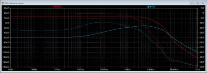
Very easy to understand. (As they are the two sides of the symetrical branches we gonna look at one of them).
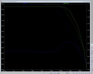
At low frequencies, there is negligible phase shifts in the feedback signal. So the differences between input and feedback signals remain constant (feedback ratio) at the output of the input stage after subtraction.
At 8KHz, we arrive at the limit, and phases begin to be affected, Feedback signal is no more perfectly in phase with the input signal. This indicate open loop bandwidth as well as feedback ratio begin to decrease. Up to 4.5MHz (in this very fast amp ;-) where there is no more gain available in the following stages (VAS+OPS), then it continue to decrease in the same time that the output level.
Output bandwidth(red) compared with this measurement (blue) will be more talkative.
You can see the real OLG in one sight.
Attachments
Last edited:
I am confused. Recieved the Kypton-ND2 today. But the BOM list that jwilhelm brought today, does not correspond to ostripper schematic in post 8603(I suppose this is his last one). Can we please have the correct BOM list.
Eivind Stillingen
Eivind Stillingen
jwilhelm
I am still confused. The attached thumbnails in your post 8689 is not the same as I get in post 8603. As an exampel: look at R1 in post 8603 =820 ohm.
In post 8689 R1=470 ohm. There are also other differences.
The thumbnail you brought up is from post 6782.
Eivind Stillingen
I am still confused. The attached thumbnails in your post 8689 is not the same as I get in post 8603. As an exampel: look at R1 in post 8603 =820 ohm.
In post 8689 R1=470 ohm. There are also other differences.
The thumbnail you brought up is from post 6782.
Eivind Stillingen
Last edited:
The schematic in post 8603 is for a different amplifier. This is Kypton-ND. That was Kypton-V. I think OS has posted a schematic with some different resistor values for the servo. R14 and R15 will need to be adjusted to suit your selected rail voltage.
As I said, the values in the BOM I posted are what I have tested and know to work. There are loads of different options possible, but I haven't personally tested them.
As I said, the values in the BOM I posted are what I have tested and know to work. There are loads of different options possible, but I haven't personally tested them.
Here's a BOM and schematic for the output board. Follow the charts on the bottom of the schematic for different output device options. The 1 Watt resistors listed should be 3 watt.
Attachments
Last edited:
Ok. Then I must rely on you. Three different threads about the same issue(Slewmaster). It is easy to get lost. Thanks.
Eivind Stillingen
Eivind Stillingen
Ostripper has a pair of these running as well. If I can find a schematic of what he's running I'll try to upload a BOM from it as well. Someone had mentioned starting a separate build thread for the Kypton-ND. This might be a good idea to avoid a lot of confusion.
Where is the point you took your AC analysis ? Right at the output of the LTP or CFA input transistor ?I have difficulty in finding resemblance.
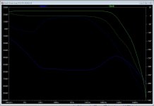
I have a new one, the servo is affecting under 10 hz or so, this is tha same plot but without the servo connected.
The plot is taken after the IPS, at the input of the folded cascode
Compared to you I do get an unexpected result, as it looks like I have more feedback available at higher frequencies and an almost linear feedback ration in the audible band...
I would have thought that the CFA would excel here.
The plot is taken after the IPS, at the input of the folded cascode
Compared to you I do get an unexpected result, as it looks like I have more feedback available at higher frequencies and an almost linear feedback ration in the audible band...
I would have thought that the CFA would excel here.
Attachments
Last edited:
jwilhelm
I am still confused. The attached thumbnails in your post 8689 is not the same as I get in post 8603. As an exampel: look at R1 in post 8603 =820 ohm.
In post 8689 R1=470 ohm. There are also other differences.
The thumbnail you brought up is from post 6782.
Eivind Stillingen
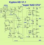
That last K-ND schema was fine tuned to give 6.5ma total VAS I.
470= 6.5 and 560R will give >7.5ma.
This change was to allow for less bias across the LED's in the cascode.
The ND works well either way , the "issue" was simulated - but I have not
experienced it in the real amp.
As long as the final VAS I is 5.5ma , how you get there is not important.
The lower current "way" is better , both in simulation and for the devices.
(Cooler).
BTW - LED versus cascode (main)current is trimmed by R24 + R25.
R25=100k will allow for .9 - 1.4ma across the red LED's.
OS
Thanks for the BOM jwilhelm much appreciated.
One thing I found during mouser window shopping - it may not seem much, but hey what the heck: the TL072IP is in fact 1/3 cheaper than the ACP variant regardless of having the same electrical properties but wider temperature range.
One thing I found during mouser window shopping - it may not seem much, but hey what the heck: the TL072IP is in fact 1/3 cheaper than the ACP variant regardless of having the same electrical properties but wider temperature range.
These BOMs are generated from my layout software and are usually whatever device was preloaded in the software with the correct footprint. Many are actually outdated parts. Any TL072 in a DIP package will work fine. Ignore the suffix on all devices. I'll try to make the BOMs a little more user friendly and add some suggested part numbers from a couple different suppliers as well, but this will take some time. I see a couple discrepancies in the output board BOM too. I'll try to fix it up as well.
Last edited:
Post 8689 (11 abover yours)... At least it seems to be the latest, as it has the 470R R1.
Suggestion to Os and Co. maybe you could release a interims 1.2 version? I know you are gonna change it sooner than later to v.2 ( at least that's what I understood) but it may help the confusion.
Suggestion to Os and Co. maybe you could release a interims 1.2 version? I know you are gonna change it sooner than later to v.2 ( at least that's what I understood) but it may help the confusion.
- Home
- Amplifiers
- Solid State
- Slewmaster - CFA vs. VFA "Rumble"