Good evening,
I'm getting boards for a stereo Slew/KND set (thank you very much evanc) and I'm filling my basket at mouser's with parts. This was when I realized that the stated 2SC3503/2SA1381 is obsolete. Many say the variants with the K-prefix are substitutes but mouser only has different grades for them. Is this going to be a problem? The grades are D for the *SC* and E for the *SA*.
Is there another alternative?
KSA1381 and KSA3503 are what these amps have been tested with. The mismatch grade can be compensated for by mismatching Q10 and Q14. The servo will also take care of any imbalance.
Hey Juan,
Great to see you got it going. I figured you would be surprised at the little mini OPS. I got the idea because of the Peeceebee. It just has one pair of latfets and is surprisingly powerful. I wanted something small to used with many IPS sections that I had built. I love it for testing new IPS sections. It seems to be more forgiving than the big Slewmaster. Anyway, have fun with it.
Blessings, Terry
Hey Juan,
Great to see you got it going. I figured you would be surprised at the little mini OPS. I got the idea because of the Peeceebee. It just has one pair of latfets and is surprisingly powerful. I wanted something small to used with many IPS sections that I had built. I love it for testing new IPS sections. It seems to be more forgiving than the big Slewmaster. Anyway, have fun with it.
Blessings, Terry
Terry one question, how the bias of the SlewMaster Mini is adjusted ?
KSA1381 and KSA3503 are what these amps have been tested with. The mismatch grade can be compensated for by mismatching Q10 and Q14. The servo will also take care of any imbalance.
Thank you. Okay on the ISP it's no problem. And on the slewmaster?
Thank you. Okay on the ISP it's no problem. And on the slewmaster?
Feedback takes care of it on the output board.
Hi Juan,
The Slew-mini OPS doesn't have any source resistors so you have to measure the current on the rails. I think I have mine set to 70mA but you can probably go higher if you like. If it is any help, my trimpot measures 1.3k as it is set now. I don't remember which IPS I last had attached to it. That does make some difference because they don't all have the same current output.
The Slew-mini OPS doesn't have any source resistors so you have to measure the current on the rails. I think I have mine set to 70mA but you can probably go higher if you like. If it is any help, my trimpot measures 1.3k as it is set now. I don't remember which IPS I last had attached to it. That does make some difference because they don't all have the same current output.
Hi Juan,
The Slew-mini OPS doesn't have any source resistors so you have to measure the current on the rails. I think I have mine set to 70mA but you can probably go higher if you like. If it is any help, my trimpot measures 1.3k as it is set now. I don't remember which IPS I last had attached to it. That does make some difference because they don't all have the same current output.
ok I will then adjusted to that setting 1.3K I still listen to the music man guitar sounds amazing 😀
Best Regards
Juan
The original spook with it's hawksford is almost the same as if you swapped the symetri VAS.
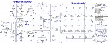
Symetri Cascode - Robust Clipping
Adding cascodes to the Symetri inputs brings the topology closer to the Spooky/Leach designs. Sims to 6ppm with 55V (~190W) into 8ohms.
Fully symmetrical topologies like the Symetri Cascode cancel out some even harmonic content which allows 5th-7th... odd harmonics to be higher than the previous 4th-5th.... even harmonics. The Sanken output transistor models reduce 3rd harmonic content in the FFT compared to the OnSemi. Go Figure.
---
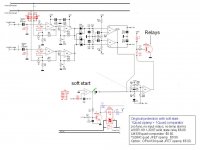
The choice in ampllifier protection circuits is driven by the OPAMP SERVO DECISION.
Amplifiers which make the commitment to support an Opamp DC Servo can economically support "high quality" protection circuits. The cost and size of the regulated +/- 15V power supply and relays(MOSFETS) for speaker and power protection dominates. High quality OPA627, OPA134/OPA2134 are selected for the DC Servo. Adding Esperado Ultimate protection with one quad opamp and one quad comparator offers high bang/buck. ($0.50 quad opamp + $0.50 quad comparator). This design can protect a 100db/w tweeter, and a 90db/w woofer.
Attachments
Symetri Cascode - Robust Clipping
Adding cascodes to the Symetri inputs brings the topology closer to the Spooky/Leach designs. Sims to 6ppm with 55V (~190W) into 8ohms.
Fully symmetrical topologies like the Symetri Cascode cancel out some even harmonic content which allows 5th-7th... odd harmonics to be higher than the previous 4th-5th.... even harmonics. The Sanken output transistor models reduce 3rd harmonic content in the FFT compared to the OnSemi. Go Figure.
---
The choice in ampllifier protection circuits is driven by the OPAMP SERVO DECISION.
Amplifiers which make the commitment to support an Opamp DC Servo can economically support "high quality" protection circuits. The cost and size of the regulated +/- 15V power supply and relays(MOSFETS) for speaker and power protection dominates. High quality OPA627, OPA134/OPA2134 are selected for the DC Servo. Adding Esperado Ultimate protection with one quad opamp and one quad comparator offers high bang/buck. ($0.50 quad opamp + $0.50 quad comparator). This design can protect a 100db/w tweeter, and a 90db/w woofer.
I made the symetri "decision". I saw your circuit ... any benefits to referencing
the cascodes from the full rails ?
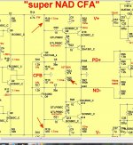
(below) I did it like the original spooky , 12V rails for both cascodes and
servo. Got the same 5-6ppm 20k as you.
Same as the spooky , but with more "robust" overload behavior.
This will be one of the 3 chosen designs (K-ND , symasui , spook V2).
OS
Attachments
Os, you could try some isolation (base stopper) at the superpair input, or, even better a low pass filter to avoid this ? (Like I did on my diamond, for the same reason: I was always afraid by the super pairs because of this).
Regarding this - (already has stoppers here !)
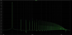
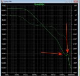
(below 1) was the original bode that worried me.
My cheap PC scope can see no issue , my zoble is cold and the OPS
is cool (no sign of anything wrong).
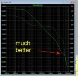
(below 2) shows the "fix" ... why not go for perfection !
What I did was just lower the VAS cascode current (LED current) to
1.1ma. Change R18/19 to 470R ,R25=100k ... total VAS I drops to
6.6ma.
subtract the lower 1.1ma through the leds gives 5.5ma "real" VAS I.
I fooled with both the super-pair basestopper and cascode stopper.
10-22R gives the least peak at 40mhz.
I really don't think even a non- corrected K-ND would have an issue ,
but this is a further refinement to this fine VAS.
Another (paranoid) tweak is to raise the value of C6-7 to 47pF , you still are >2mhz
ULGF and 320V/us slew. 8 ppm @ 20K 200W jumps to 12ppm , as well.
But all those specs are crazy good ... regardless.
Edit - The R22 I is 6.6ma after the "fix" (tweak) , all other currents stay the same.
VAS as a whole runs even cooler.
\\OS
Attachments
Last edited:
I saw your circuit ... any benefits to referencing
the cascodes from the full rails ?
I like how my cascode circuit topology tracks the diff-pair summation point because this sims well with temp drift and transistor variations.
I favor a separate +/- 15V supply for the DC servos plus the protection circuits. To control the soft-start function, this protection supply must reach stable power-up several seconds before the main supply, and also stay stable after opening the soft-start and speaker protection relays. In the SpookyV2 circuits, a reversed bias PN junction in the power amp might affect these protection supply/circuits.
What is your method of making LT bode plots, I normally use the Loopgain 2 from the LT examples. I have found that to be quite reliable
Ostripper,
try decrease C6-C7 to 10pF and run Bode Plot again ( maybe it will be perfect )
That will raise UGLF to 4.3mhz but kill phase margin.
It does round off that step a little , BTW.
You could counteract this with more diamond or super-pair degeneration ,
but that will cut into the slew rate.
All these factors are compromises between speed , stability , and gain
margin at 20K.
39-47p (C6-7) is a "happy medium" - >300 slew ,80+ margin , 8-10ppm/20k.
OS
What is your method of making LT bode plots, I normally use the Loopgain 2 from the LT examples. I have found that to be quite reliable
Even as I know the Tian , a simple CFA like this is no different from
a simple LIN VFA .... just need to break NFB and use "V(vout)/-V(a)".
Tian is good for TMC or a design like "kypton V" (sansui 3 stage) with its
compound compensation(s).
OS
I like how my cascode circuit topology tracks the diff-pair summation point because this sims well with temp drift and transistor variations.
I favor a separate +/- 15V supply for the DC servos plus the protection circuits. To control the soft-start function, this protection supply must reach stable power-up several seconds before the main supply, and also stay stable after opening the soft-start and speaker protection relays. In the SpookyV2 circuits, a reversed bias PN junction in the power amp might affect these protection supply/circuits.
Have you heard Keentoken and Cordell's thermal model discussion ?
IKF and XTB in some of our models is wrong - thermals are inconsistent
with the real devices. This was in the last few posts of Bob's book thread
,I think.
I have never had much confidence in LT thermal modeling , better to
observe the real circuit for that.
OS
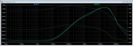
ostripper, Can-you help-me, trying some quick simulations, in giving-me your opinion on my method to evaluate OLG in an closed loop system without breaking NFB ?Even as I know the Tian , a simple CFA like this is no different from a simple LIN VFA .... just need to break NFB and use "V(vout)/-V(a)"
I just make an AC analysis right at the output of the IPS. (IRL or sim)
You will see a flat bandwidth up to the frequency where phases / levels begin to unmatch between input signals and feedback ones. After this point, the level begin to increase up to the point where the amp has no more gain available.
it gives something like this (blue and green are the two branches):
Attachments
Last edited:
ostripper, Can-you help-me, trying some quick simulations, in giving-me your opinion on my method to evaluate OLG in an closed loop system without breaking NFB ?
I just make an AC analysis right at the output of the IPS. (IRL or sim)
You will see a flat bandwidth up to the frequency where phases / levels begin to unmatch between input signals and feedback ones. After this point, the level begin to increase up to the point where the amp has no more gain available.
it gives something like this (blue and green are the two branches):
I might not know the Tian that good 😱 . I have used it to explore the
TMC.
Plotting Loop Gain Using the Tian Method - Spring 2011
Tian's method can measure the "backwards" transmission on a complex
feedback method. Circuits parameters are least affected by the tian.
(better for checking "loops within a loop")
But , here - https://sites.google.com/site/frankwiedmann/loopgain
The old middlebrook method is said to be sufficient in most cases.
I must admit Dadod and other members explored this further ... while I
devoted more time to create the real amps.
I must "catch up" (google is my friend). 😀
OS
- Home
- Amplifiers
- Solid State
- Slewmaster - CFA vs. VFA "Rumble"