Gerbers and drill data....
I just don't know what the (>>>>) outputs are ??
I edited JK's excellent note and created outputs to match.
Evan , what color ?- 2oz is also an option (60A rails😀)???
OS
Plate through hole and non-plate through hole. The board shops I've dealt with don't require this. They just want one Excellion file for all holes normally.
Plate through hole and non-plate through hole. The board shops I've dealt with don't require this. They just want one Excellion file for all holes normally.
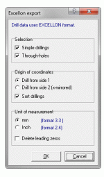
Since you know .... 😀 , how about the excellon standards (example below).
Do I have the right defaults ?
Thanks..
OS
Attachments
Since you know .... 😀 , how about the excellon standards (example below).
Do I have the right defaults ?
Thanks..
OS
Looks good. I've never had any issues using inch dimensions either.
JW is right, the 'extra' drill files just separate Plated Through Holes and Non-Plated Through Holes. I only output those in case the board house has a preference or specific requirement. I also specified all dimensions in imperial (I always tied to work exclusively on a 0.050" grid) including the drills.
Sprint's defaults are fine, don't jack with the settings unless you know specifically you need something otherwise.
A reminder too, the specified size for a PTH is after plating. The board house will slightly up-size the drill so the finished hole is as specified. You, the designer, don't have to make allowances for that.
I went over for everything .8/1/1.6/2.2mm -those 4 sizes only.
Your PCB's were right on - the small resistors nearly "squeak" when you
rework them. You did allow output transistor "slop" , but I went .4mm over
ON's 1.2mm spec.
Just about everything has .2 -.3mm extra. They should just drop out on a rework.
OS
I could not use those. There are silkscreen on pad errors ...
Through-hole double sided will show this as an error as it conflicts with the soldermask.
Edit - when you make them , test F12 (or not) , run your macro template through a DRC check.
Make a macro universal 1 or 2 sided by default.
OS
I will do that tomorrow is kind of late 😛 yes I know the macros need to be free of silkscreen on top of pads 🙂 yes I will check with DRC good tool 😛
Attachments

Using the pcb way online estimator it looks like 2oz copper adds about $1.00 per board.
Going from 1.6mm thick to 2mm thick also adds a bit more then $1.00 per board.
Gold plating adds about $1.00
This is assuming 40 boards produced.
I would think 1.6mm thick 2oz copper would be good...but you tell me.
In all still not a very expensive part of the amp.
color.....I'm happy with green but could be easily be talked into any.
E
Using the pcb way online estimator it looks like 2oz copper adds about $1.00 per board.
Going from 1.6mm thick to 2mm thick also adds a bit more then $1.00 per board.
Gold plating adds about $1.00
This is assuming 40 boards produced.
I would think 1.6mm thick 2oz copper would be good...but you tell me.
In all still not a very expensive part of the amp.
color.....I'm happy with green but could be easily be talked into any.
E
I have all my gerbers/excellon ready to zip.
These are yours and the forum's , my entry on the color is just an edit away.
I don't even know what my color choices are (JK /JW ?? ).
The layout / design is the main player - color is just subjective. I listen to the output
... not stare at the workings ... 😀
1$ extra for each of those embellishments is quite reasonable.
OS
Colours for the solder mask will vary by vendor, but generally most offer green, blue, red, black and white, with some offering a few others. There are usually fewer options for the silk screen. White silk screen will usually be used on everything except a white mask, where black will be used instead. I agree with OS, old-fashioned green and white suits me since once the build is complete you can't see it anyway.
I doubt even 2oz copper is even really required, and it is almost always a 'plate-up' anyhow since native 2oz metal is more expensive and slower to process. Board houses often use 1/2oz to speed processing and electroplate the rest on later, even with 1oz boards. Certainly no harm in ordering 2oz copper, though I have done it and have seen that it can cause the silk screen to become distorted.
The 1.6mm FR4 as a substrate is a very common standard. I doubt there is any real advantage to ordering a thicker material as it isn't being used for its mechanical properties anyway. Why pay extra, even if only a little, for something that is of no real benefit? Of course, one can choose as one pleases on that option, but it wouldn't be where I'd choose to spend extra.
Hot air leveled tin (HAL / HASL) is really the only required finish, gold won't make the connections any better and can even make the solder brittle joint under certain circumstances. Unless you are going to store the boards sea-side for a few years before using them I wouldn't bother. My order of Spooky IPS boards was gold plated unintentionally by the board house, so on those it was a free added bonus.
That's my 2¢ on board options as my experience relates to them, but I'm not an expert either.
Gold is a good option for fine smt parts. The thickness of the HASL can make the edges of the silk messy. For through hole HASL is fine though. Most of us use lead solder anyways. There's not really any advantage to adding another dissimilar metal to our weld joints.
Pre-drivers and drivers
I have been looking through some data sheets and I noticed Fairchild makes their 2sc5200/2sa1943 copy in a to-220 package. They are FJP5200 and FJP1943. These look like they could be an interesting choice for someone wanting a to-220 driver more powerful than MJE15032/MJE15033. They might even be usable as outputs if the tabs are soldered directly to a copper heat spreader.
Toshiba 2sc4793/2sa1837 look to be the best alternative for someone who doesn't want to use ksc3503/ksa1381 for pre-drivers. If one is using under 70V rails then Fairchild ksc2690/ksa1220 or Sanken 2sc4883/2sa1859 look to be good choices too. Just beware that some of these have pin-outs that are backwards compared to ksc3503/ksa1381.
By Jkeutemann - That's my 2¢ on board options as my experience relates to them, but I'm not an expert either.
You SURE sound like one ! Very helpful all the way.
You are right on and concise - thanks !
I would of had to do quite a bit of extra research on these "finer" points. 😱
OS
I have been looking through some data sheets and I noticed Fairchild makes their 2sc5200/2sa1943 copy in a to-220 package. They are FJP5200 and FJP1943. These look like they could be an interesting choice for someone wanting a to-220 driver more powerful than MJE15032/MJE15033. They might even be usable as outputs if the tabs are soldered directly to a copper heat spreader.
Toshiba 2sc4793/2sa1837 look to be the best alternative for someone who doesn't want to use ksc3503/ksa1381 for pre-drivers. If one is using under 70V rails then Fairchild ksc2690/ksa1220 or Sanken 2sc4883/2sa1859 look to be good choices too. Just beware that some of these have pin-outs that are backwards compared to ksc3503/ksa1381.
Those FJP's might be good for a 3 pair 4R OPS. I'd stick with the TO-3P's at
5 pair (or MT-200).
The 2sc4793/2sa1837 is the original Harmon kardon driver set. It would be good
to drive the VFET output option , as they would be driving gate capacitance only.
As predrivers , yes ... those toshiba's would work ,but only 2mA ? better to use
some TO-92L high fT japanese substitute.
Any higher gain device can be the multiplier choice. Only a few volts drop mean
they too ... can be a TO-92L type device.
PS - nice to be able to talk all the options (2-5pair/BJT-VFET) on one creation.
No more "baby" - monster , etc ....
OS
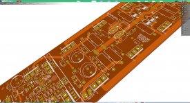
Here they are Evan (chinese pirates😀) .....
Is there any 3rd party gerber/drill viewer that can confirm the work ?
I also included the sprint .lay so one could get the free viewer to look or
edit.
OS
Yes mister OS there's a software that you can place gerbers and will actually see it in 3D also you can check LS = pitch distance too 🙂 check it out
ZofzPCB: FREE 3D Gerber Viewer
Regards
Juan
OS did you forgot to place outline ? 🙂
here is a sort like a preview of how it looks like, just got to play with software a little bit 😛
Regards
Juan
here is a sort like a preview of how it looks like, just got to play with software a little bit 😛
Regards
Juan
Attachments

Last edited:
Abort launch !! Houston
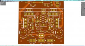
I loaded your gerber drill into gerbtool. I see issues with your drill data, seems some/many parts are missing a proper drill size or the drill size is way too small.
I see, a partial list, of these comps having issues.
C16,18 ...
R132-135 ...
D104b,105b,D107b ...
Q101,102,107b ...
You should have been able to check these out before you generated the drill data, that is if your s/w is any good. Turn on only your drill layer and top pads to check. You should be able to see the drill diameter, the pad diameter(annual ring) and even the SM relative to the pad which i usually use 6 mil or 0.15mm over pad if using lpi sm which is pretty much std these days.
Also are you not able to generate a fab drawing and place a drill schedule which calls out drill sizes and matches them to a symbol that represents the drill hit location.
On the other issue with drills. if you want npth's you should send a separate drill file just for them and have notes in the drill schedule indicating as such. Some el cheapo pcb fab houses only do PTH as NPTH are a secondary op. that they wish to bypass so they can continue to be called el cheapo.
I will look further ...
oh boys I see lots of other problems too
SMD mask top should be merged with soldermask top, might be a setup in your gerb generator
have you actually fab'd anything with this s/w package before?
Last edited:
- Home
- Amplifiers
- Solid State
- Slewmaster - CFA vs. VFA "Rumble"