Would the common bus bar be the best connection to the Collectors of all the output devices and eliminate the need to have a trace on the PCB for the rail voltages? Hook the bar up to the power supply directly...then just insulate the bar from the heat sink.
Would the common bus bar be the best connection to the Collectors of all the output devices and eliminate the need to have a trace on the PCB for the rail voltages? Hook the bar up to the power supply directly...then just insulate the bar from the heat sink.
Yes, it's possible to do, with some copper bar, isolated from the heatsink. PSU companies use many of this copperbars in large DC power supply.
Sajti
Where did You get this values?
Sajti
Either from the table of Selfs book -https://books.google.com/books?id=7djSyLcX4coC&pg=PA615&lpg=PA615&dq=mt-200+device&source=bl&ots=D0_C43SJfd&sig=2Jx7hnHyIme3EFdCtawST-Qe5c8&hl=en&sa=X&ei=3c5tVYSNBIPosAXYloPgDw&ved=0CDgQ6AEwBA#v=onepage&q=mt-200%20device&f=false
Or the datasheets - some list it , some don't.
Self generalized by package , individual devices may vary slightly by
manufacture.
OS
Last edited:
Self generalized by package , individual devices may vary slightly by
manufacture.
OS
I guess, that it's a wrong estimation...
Sajti
Attachments
I guess, that it's a wrong estimation...
Sajti
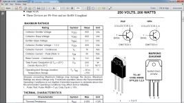
But those devices must have larger dies.
The .43 of the MGxxxx must mean a HUGE die (10mm) !! 😱
typical to-3p/264 has 6mm.
OS
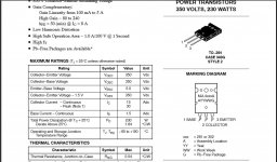
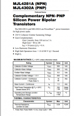
MJL4281
MJL4281 = 6mm die , most likely like Self's example .7C/W.
MJL4281 = 6mm die , most likely like Self's example .7C/W.
.54C/W
Attachments
But those devices must have larger dies.
The .43 of the MGxxxx must mean a HUGE die (10mm) !! 😱
typical to-3p/264 has 6mm.
OS
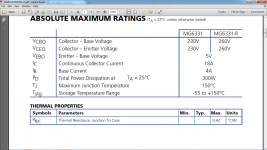
I think, that junction to case is not really important, as we are not able to do anything with it. If You have a 200W device it will be 0.625K/W, if You have 150W device, it will be 0.83K/W, and both is true for any plastic cases.
What is more important is the case to sink. And this is the race, where the MT200 is the absolute winner in the plastic group.
Sajti
.54C/W
Self is wrong , again. That's >30%... Big de-rating difference.
So if the modern plastics I've seen are all that "off",
the MT's must be in the .4x range , as well.
Thermal epoxy on the dies must be better now.
OS
You risk a dead horse head in your bed ! 🙂Self is wrong , again.
Self is wrong , again. That's >30%... Big de-rating difference.
So if the modern plastics I've seen are all that "off",
the MT's must be in the .4x range , as well.
Thermal epoxy on the dies must be better now.
OS
I thinks that the epoxy is same, as the maximum die temperature is still 150C (metal case TO-3 has 200C).
The MT's are 0.625K/W as they are 200W devices. (Tjmax-Tcase)/Pdmax. And this valuse always given with Tc=25C. So 150-25/200=0.625. Anyway this value is NOT as much important!!!
Using mica insulator makes 0.25K/W with MT200, but 0.5K/W with MT100/TO-3P. And this is the real advantage! If we compare the 200W MT200 with 200W MT100:
Let's check with real conditions: Heatsink temperature -let say-50C. Pdmax= (150-50)/(0.625+0,25)=114W with MT200, and Pdmax=(150-50)/(0,625+0,5)=89W with MT100. This is why the MT200 better.
Sajti
Using mica insulator makes 0.25K/W with MT200, but 0.5K/W with MT100/TO-3P. And this is the real advantage! If we compare the 200W MT200 with 200W MT100:
Sajti
Ahh , area of the interface material (mica/compound) I see !😎
Then 5 to-3p's in a row on a 35X125mm copper plate with another
35X125mm mica underneath would nearly have a thermal resistance equal to
5 MT's,
Thanks.
Ahh , area of the interface material (mica/compound) I see !😎
Thanks.
The bigger area is big big advantage. It's almost as big as the TO-3 version. Sanken want to make a plastic case, which is easy to use, but they have the termal parameters close to the full metal package.
Sajti
The die is mounted on the metal tab on the rear of the transistor. Here's a picture of some MT-200s I exploded.
A couple years a go it happened with me to. The plastic exploded into my face.
And was not eBay item.😛😡
Purchased here in Toronto at local store.
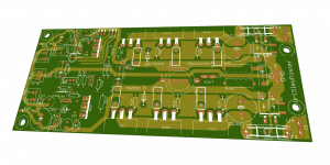
So after all OS advices i send UniSlewMaster gerber files to PCB manufacturer... So choice for output can be 3 pairs BJT (TO264/TO3P), 2 pairs BJT MT200 or 3 pairs VFET (TO247)
Attachments
Last edited:
Idefixes,
What is the purpose of the many small holes in the center section where I suppose you are placing an inductor/
What is the purpose of the many small holes in the center section where I suppose you are placing an inductor/
A couple years a go it happened with me to. The plastic exploded into my face.
And was not eBay item.😛😡
Purchased here in Toronto at local store.
I wanted to blow these up. I wanted to see first hand what my protection circuit would do when an amplifier self destructed. Everything went as I had hoped.
Idefixes,
What is the purpose of the many small holes in the center section where I suppose you are placing an inductor/
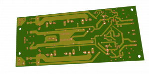
Those are Vias to connect to the bottom of the board.
Those are Vias to connect to the bottom of the board.
That's it. Top layer is broken by GND return from driver area.
Marc
- Home
- Amplifiers
- Solid State
- Slewmaster - CFA vs. VFA "Rumble"