I export at least the following into a 'for manufacture' package:
1) Outline
2) Top Copper
3) Bottom Copper
4) Top Solder Mask
5) Bottom Solder Mask
6) Top Silk Screen
7) Excellon with PTH only
8) Excellon with NPTH (plain drillings) only
9) and an Excellon file with all drillings together
Different vendors want different things in the drill file(s), so doing as above will give them the pick of what they need / want.
Before you do ANY of the exports, do use the DRC tool to ensure you have no issues like silk on pad, clearance problems, drillings too close etc. to help ensure the design will go through manufacture without issue.
No problem for 1-9. No problem with silk on pad .... I get "drilling too close"
on oblivious good pads (larger pads with larger holes) .... can't figure why ??
OS
No problem for 1-9. No problem with silk on pad .... I get "drilling too close"
on oblivious good pads (larger pads with larger holes) .... can't figure why ??
OS
Post a snippet of the image showing the error. Remember a 'plain drilling' is done on the bottom copper layer with a pad where both values (pad diameter and drilling) need to be identical.
Post a snippet of the image showing the error. Remember a 'plain drilling' is done on the bottom copper layer with a pad where both values (pad diameter and drilling) need to be identical.
Thanks ...JK , I deduced the issue. A couple of my macros used over lapping
pads as components. I fixed the macro , warning goes away.
Ran DRC on my macro collections to weed out any offenders.
If you have a DRC issue on a saved macro , it don't go away.
The plain drillings are correct (exact identical), Good to know about
the last (manufacturing) step.
OS
Ah, yes. I did that to myself early on when learning the software. I draw all my own makros and keep them in their own folder. I found a number of the provided ones and optional downloads of makros are poor in quality and so don't use them now.
Learned a lot.
CAD is good. Especially when it can fix or identify screwups. 😀
Down to 0 DRC errors.
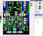
Strange (below-circled), SMD option pads do not overlay C1 tracks. Had to make
C1 tracks , as SMD pads will show a error if there is a through-hole on
them. Any workaround for this ?
This "arc welder" HAS to be perfect , with that much dangerous power.
Both me and Evan run 800-1Kva 75-82V PS's , not for the "faint of heart".
Some good compromises arise .... driver decoupling of 470u / 2.2R will
keep the same R/C of 100/10 or 220/4.7. More driver I with the same RC.
Choice of the 2 caps for ESR is also recommended.
Just a bit more "tweaking".
PS - JK , should I just output ALL gerber/excellon data ? And is there a way
to do it all at once instead of all those individual exports ??
OS
CAD is good. Especially when it can fix or identify screwups. 😀
Down to 0 DRC errors.
Strange (below-circled), SMD option pads do not overlay C1 tracks. Had to make
C1 tracks , as SMD pads will show a error if there is a through-hole on
them. Any workaround for this ?
This "arc welder" HAS to be perfect , with that much dangerous power.
Both me and Evan run 800-1Kva 75-82V PS's , not for the "faint of heart".
Some good compromises arise .... driver decoupling of 470u / 2.2R will
keep the same R/C of 100/10 or 220/4.7. More driver I with the same RC.
Choice of the 2 caps for ESR is also recommended.
Just a bit more "tweaking".
PS - JK , should I just output ALL gerber/excellon data ? And is there a way
to do it all at once instead of all those individual exports ??
OS
Attachments
Do you have the SMT pads set as through hole? I think in 6 they show up the same colour as traces.CAD is good. Especially when it can fix or identify screwups. 😀
Down to 0 DRC errors.
Strange (below-circled), SMD option pads do not overlay C1 tracks. Had to make
C1 tracks , as SMD pads will show a error if there is a through-hole on
them. Any workaround for this ?
This "arc welder" HAS to be perfect , with that much dangerous power.
Both me and Evan run 800-1Kva 75-82V PS's , not for the "faint of heart".
Some good compromises arise .... driver decoupling of 470u / 2.2R will
keep the same R/C of 100/10 or 220/4.7. More driver I with the same RC.
Choice of the 2 caps for ESR is also recommended.
Just a bit more "tweaking".
PS - JK , should I just output ALL gerber/excellon data ? And is there a way
to do it all at once instead of all those individual exports ??
OS
CAD is good. Especially when it can fix or identify screwups. 😀
Down to 0 DRC errors.
Strange (below-circled), SMD option pads do not overlay C1 tracks. Had to make
C1 tracks , as SMD pads will show a error if there is a through-hole on
them. Any workaround for this ?
This "arc welder" HAS to be perfect , with that much dangerous power.
Both me and Evan run 800-1Kva 75-82V PS's , not for the "faint of heart".
Some good compromises arise .... driver decoupling of 470u / 2.2R will
keep the same R/C of 100/10 or 220/4.7. More driver I with the same RC.
Choice of the 2 caps for ESR is also recommended.
Just a bit more "tweaking".
PS - JK , should I just output ALL gerber/excellon data ? And is there a way
to do it all at once instead of all those individual exports ??
OS
Yes, there should be no drilling within an SMD pad. Where I needed an accessible option I simply made the traces from the SMD pad to the through hole device on the top copper layer, otherwise you could use a via to change layer. Or simply put the option on the bottom, as the builder should know wether he / she in invoking a given option while stuffing the board, no need to access it from the top really.
Sprint 6 can do the gerbers in one export and individual excellon exports, but in Sprint 5 it is a one-at-a-time deal. No biggie as you only do it once. For a board like this the prior list of layers is all anyone needs.
OS, You think that is enough power to drive a couple of 6 1/2 cones! Five pairs of MT200 outputs, oh my. 😀
It is looking more and more like a 2-pairs board and a way to limit a single pair will be all I need. Now if I could do that on a single board that would be nice, a biamp board with electronic xo. the best of all your work. 😎
It is looking more and more like a 2-pairs board and a way to limit a single pair will be all I need. Now if I could do that on a single board that would be nice, a biamp board with electronic xo. the best of all your work. 😎
Do you have the SMT pads set as through hole? I think in 6 they show up the same colour as traces.
I'll try that . (F12 em')Thanks.
OS
Yes, there should be no drilling within an SMD pad. Where I needed an accessible option I simply made the traces from the SMD pad to the through hole device on the top copper layer, otherwise you could use a via to change layer. Or simply put the option on the bottom, as the builder should know wether he / she in invoking a given option while stuffing the board, no need to access it from the top really.
Sprint 6 can do the gerbers in one export and individual excellon exports, but in Sprint 5 it is a one-at-a-time deal. No biggie as you only do it once. For a board like this the prior list of layers is all anyone needs.
Now at least I know "something" 😱 .
So , Just the layers I use (C1/2 and S1) , the masks , drill data (excellon in mm ?) and finally the milling data - which one ?
Label them for what they are ?
Any other data would be Zero ....
OS
OS, You think that is enough power to drive a couple of 6 1/2 cones! Five pairs of MT200 outputs, oh my. 😀
It is looking more and more like a 2-pairs board and a way to limit a single pair will be all I need. Now if I could do that on a single board that would be nice, a biamp board with electronic xo. the best of all your work. 😎
This project has advanced enough where it would just take incentive to
create a 2 mini amp "all in one" PCB. After I successfully master the
production end of sprint , I have it covered.
Now , on the "pitchfork linestage" , I did the simulations ... Jeff (Jwilhelm)
did the layout - he is excellent at high density !!! 😱
Sub amp , Jeff took my 2 part wolverine/OPS and ended up with an amp
that blew up the sub box and shook a warehouse. We are 100% with
SOTA class AB !
OS
Now at least I know "something" 😱 .
So , Just the layers I use (C1/2 and S1) , the masks , drill data (excellon in mm ?) and finally the milling data - which one ?
Label them for what they are ?
Any other data would be Zero ....
OS
I have a package of files posted in a ZIP file HERE . Have a look at what I packaged up. Myself and a number of other members have ordered boards with these files without any complaints.
I have a package of files posted in a ZIP file HERE . Have a look at what I packaged up. Myself and a number of other members have ordered boards with these files without any complaints.
Ok , looks like good example. If I just use your 5P as an example ... I should be good
to go.
One question , do I need the PDF drill chart ? .. I don't see that as an export
()in sprint.
Fab notes is a good idea to be verbose on the requirements !
PS , I forgot you were already on version 2.x ..... this one might have to
be V3.0 to avoid confusion. 😀
OS
Fab notes is actually a bad idea if you are dealing with China. It causes errors with the language barrier. Everything they need is in the gerber files.Ok , looks like good example. If I just use your 5P as an example ... I should be good
to go.
One question , do I need the PDF drill chart ? .. I don't see that as an export
()in sprint.
Fab notes is a good idea to be verbose on the requirements !
PS , I forgot you were already on version 2.x ..... this one might have to
be V3.0 to avoid confusion. 😀
OS
The shops I've dealt with only require one drill file. They assemble the files in software and are able to figure out what holes are straight drill or plate through from there.
Last edited:
Ok , looks like good example. If I just use your 5P as an example ... I should be good
to go.
One question , do I need the PDF drill chart ? .. I don't see that as an export
()in sprint.
Fab notes is a good idea to be verbose on the requirements !
PS , I forgot you were already on version 2.x ..... this one might have to
be V3.0 to avoid confusion. 😀
OS
No, the drill chart is not a requirement in most cases. The drill chart is one of the print options, not an 'export' per-se.
I like to include a fabrication notes file, if there is an error I have some proof of what my expectations were.
Keep it up guys. I don't know why you would need to look at another amp thread after this, it seems you have covered all the bases here.
Different vendors can have different requirements. The export needs to be generic and complete, IMHO. That way the person ordering has the resources to submit what ever their choice of vendor needs.
I just make sure I name things clearly so if renaming is needed there is no guesswork. Every reference I have looked at suggests a fabrication notes file, but then if I were ordering I'd just write one myself if it were not provided.
I just make sure I name things clearly so if renaming is needed there is no guesswork. Every reference I have looked at suggests a fabrication notes file, but then if I were ordering I'd just write one myself if it were not provided.
Jason was dealing with a larger scale production shop. I've dealt with a few different smaller prototype shops. If they are good with English, fab notes are fine. If you read through the thread on PCBWay, anyone having problems usually had issues with something explained in the fab note instead of being properly drawn in the software.
Pretty much everything in Jason's fab notes is on the order page of the fab shop's webpage so his shouldn't cause any problems.
Pretty much everything in Jason's fab notes is on the order page of the fab shop's webpage so his shouldn't cause any problems.
Of course both Jeff a myself have ordered boards without issues using our own approaches, so a decent board house is clearly capable of interpreting what is provided. My 2 cents.
- Home
- Amplifiers
- Solid State
- Slewmaster - CFA vs. VFA "Rumble"