Thanks JW,
I guess you need that many to have enough surface area for a good connection through the vias.
I guess you need that many to have enough surface area for a good connection through the vias.
So after all OS advices i send UniSlewMaster gerber files to PCB manufacturer... So choice for output can be 3 pairs BJT (TO264/TO3P), 2 pairs BJT MT200 or 3 pairs VFET (TO247)
So is this board like OS's "Slew Baby" board, or does this board bring a lot of improvements to the table?
Thanks...
Terry,
That's pretty good. I guess that is the express way to let the
smoke out of those parts...All at once?
I had a question regarding the square wave testing that you do.
After you determine the clip point of the amp and back it down
to ID the max power...How do determine where you are going
to set your signal for the square wave?
Do you go down a set voltage or dB?
Terry,
That's pretty good. I guess that is the express way to let the
smoke out of those parts...All at once?
I had a question regarding the square wave testing that you do.
After you determine the clip point of the amp and back it down
to ID the max power...How do determine where you are going
to set your signal for the square wave?
Do you go down a set voltage or dB?
I set the square wave output to 10vac @ 1khx. I leave it at that output through out the test. That way I know I'm not going to smoke my zobel resistor. I suppose it might give different results at a higher voltage. I know the VSHA ECC88 IPS was showing different at higher level. :Maybe I should check for that more often.
Blessings, Terry
So is this board like OS's "Slew Baby" board, or does this board bring a lot of improvements to the table?
Thanks...
It's in the range of slewmaster (=>3 pairs OP slewbaby has 2) with ability to use VFET (hosting Valery modifications to Use Vfet : jumpzr to switch from EF3 to EF2, led in the Vbe multiplier, diode protection,....) The layout take care from OS advices : bigger main caps decoupling arrange in serie (no current return on track), vbe multiplier transistor near OPS, V rail on both side....
Marc
So is this board like OS's "Slew Baby" board, or does this board bring a lot of improvements to the table?
Thanks...
They are all the same , A modifed (harmon kardon) H/K680 triple emitter follower
output stage.
Read the reviews for the HK - Harman Kardon HK 680
That's what I did , I own one - I copied it. It's 20 years old , even.
Slew baby , V1/2 ..... if you use the toshiba 1837/4793 as drivers
and the Sankens - you even have an EXACT clone.
Other builders (and me) have used huge (output) drivers to "magnify"
this amp.
That's it , different power levels only (scalability).
OS
Hi OS ,is this the final version ?Yes , and ask your peers for evaluation/critic.
I even like it better with Jwilhelms advice added. Looked at more OPS's
and read some Slone. 😎
Now it looks "mean".
Has those Keystone "arc welder" hookups - and the molex for protection. NFB is right. A perfect star (G1).
All is below , I think it's 100%.
OS
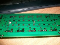
I see that decoupling electrolytics(for each trans.) aren't used here.That mean not to use those in the old vers. pcb?
They are all the same , A modifed (harmon kardon) H/K680 triple emitter follower
output stage.
Read the reviews for the HK - Harman Kardon HK 680
That's what I did , I own one - I copied it. It's 20 years old , even.
Slew baby , V1/2 ..... if you use the toshiba 1837/4793 as drivers
and the Sankens - you even have an EXACT clone.
Other builders (and me) have used huge (output) drivers to "magnify"
this amp.
That's it , different power levels only (scalability).
OS
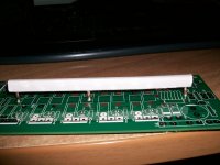
Hole For NJW or Sanken MT100 driver are in but i put TO220 hole for 1837/4793 too. I have some in stock. Could they match with 2 pair MT200 OP and +/-50Vdc rail for 4 Ohms use?
Marc
Hi OS ,is this the final version ?
I see that decoupling electrolytics(for each trans.) aren't used here.That mean not to use those in the old vers. pcb?
In his OPS evolution OS delete them and put bigger main caps mm ->18mm
Marc
Hi OS ,is this the final version ?
I see that decoupling electrolytics(for each trans.) aren't used here.That mean not to use those in the old vers. pcb?
They basically just add capacitance to the main ones. There is a compromise
involved with them.
While they may smooth sharp current spikes at the collectors ,
having that returned down long traces to the G1 ground star is a long loop area.
PS - don't use under 1uf for the V1.x PCB's .... L + C can "ring" with the
small value.
On V1 , I also combined the driver decoupling return down these same traces.
The driver decoupling is an R/C , and is far less current. It's long loop area
(distance) is not as critical. V2 has JUST the driver decoupling returns (better).
I also weighed in similar layouts. Pass X250/350
Accuphase , even the "golden amp" ... just has the main decoupling.
Below 1 and 2 -
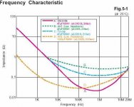
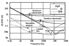
(Below 1) - is a 1000uf electro (gold line) ... matched with ( 2) , a quality film or
ceramic. Leaded monolithic ceramic seems to be best (below 3).
.02 -05uf gives the broadest range to combine with the electro's ESR.
In the end , the rails have milliohm level ESR between .01HZ and 100mhz.
Full decoupling from PS fluctuations to radio frequencies.
Short of a full regulated 10-20A supply 😀😀 , this is the best we can do.
Luckily, we have the cap multiplier and the IPS's PSRR working for us.
OS
Attachments

Thanks,practical speaking .What to do in first version?Is a good practice increasing the main decoupling (1000uF)and not use 22uF for each trans?They basically just add capacitance to the main ones. There is a compromise
involved with them.
While they may smooth sharp current spikes at the collectors ,
having that returned down long traces to the G1 ground star is a long loop area.
PS - don't use under 1uf for the V1.x PCB's .... L + C can "ring" with the
small value.
On V1 , I also combined the driver decoupling return down these same traces.
The driver decoupling is an R/C , and is far less current. It's long loop area
(distance) is not as critical. V2 has JUST the driver decoupling returns (better).
I also weighed in similar layouts. Pass X250/350
Accuphase , even the "golden amp" ... just has the main decoupling.
Below 1 and 2 -
(Below 1) - is a 1000uf electro (gold line) ... matched with ( 2) , a quality film or
ceramic. Leaded monolithic ceramic seems to be best (below 3).
.02 -05uf gives the broadest range to combine with the electro's ESR.
In the end , the rails have milliohm level ESR between .01HZ and 100mhz.
Full decoupling from PS fluctuations to radio frequencies.
Short of a full regulated 10-20A supply 😀😀 , this is the best we can do.
Luckily, we have the cap multiplier and the IPS's PSRR working for us.
OS
Thanks,practical speaking .What to do in first version?Is a good practice increasing the main decoupling (1000uF)and not use 22uF for each trans?
on my 3 pair builds , I just augment with a 100u/100V pair halfway down the rail.
@600uf X 2 for the whole OPS. Works fine !!
PS - For "anal" ESR , I've seen a 470u electro /1- 10u electro / .02-.1u
ceramic... all in parallel. The smaller electro "fills the valley" between the big
electro - ceramic. Sort of like a 3 way speaker Xover.
OS
Christmas in June...
What are you going to do for boards ?
I VERY slightly updated my V2 .lay for the PCB. Faston to connect G2 - G1.
C110 - 113 were mislabled ... etc.
The present V2 post is electrically correct , just those slight screen side
errors.
I could even add things you want , evan. BTW , size is EXACT 254 X 76.2mm.
All holes line up with V1 , as well.
OS
Publish gerber / excellon files when the art is complete, then folks can order boards if they wish.
Publish gerber / excellon files when the art is complete, then folks can order boards if they wish.
Just C1/2 and S1 gerber data and the excelon drill data ?
Edit - solder masks , as well ??
OS
Terry,
The reason I ask is I went through and did my preliminary square wave test
with my MC250 McIntosh. I'd post some pics, but my camera ran out
of juice during my left channel testing.
Where do you replace the zoebel and value?
Oh, is that the one in the link that is in series with the load?
From the link 8 ohm is load, 47.8 Kohm for 50 W amp in series.
Kid ran off with or the wife cleaned/organized and I cant find the
proprietary USB charger...it is at the Sony end.
It didn't fare to badly at the 50Hz, 1kHz and 10kHz
but the square started rounding above 20kHz.
50kHz and 100kHz weren't so good.
I found and old set of tests that the Federal
Trade Commission required from at least 1966 onwards.
Here is a link to Tektronix document from 1974.
Cookbook of Standard Audio Tests - LINK
Square wave testing is towards the end 2/3rd maybe.
Also, if you want to do some of the FFT type test
and plotting...there is the QA400. It's not bad for the
price under $200 for audio use. It does about 10 Hz to
24 KHz. It is USB, but because it has it's own hardware
interface you don't have to worry about buying a separate
audio card etc. $100 - $250 for a good used interface card.
QuantAsylum - LINK
Works on a variaty of platforms too. Win 8x, win 7, vista.
So instead of a few $1,000 it is small lightweight, portable too.
Last edited:
Just C1/2 and S1 gerber data and the excelon drill data ?
Edit - solder masks , as well ??
OS
I export at least the following into a 'for manufacture' package:
1) Outline
2) Top Copper
3) Bottom Copper
4) Top Solder Mask
5) Bottom Solder Mask
6) Top Silk Screen
7) Excellon with PTH only
8) Excellon with NPTH (plain drillings) only
9) and an Excellon file with all drillings together
Different vendors want different things in the drill file(s), so doing as above will give them the pick of what they need / want.
Before you do ANY of the exports, do use the DRC tool to ensure you have no issues like silk on pad, clearance problems, drillings too close etc. to help ensure the design will go through manufacture without issue.
I was going to ask if you were happy with your last version....now I don't have to. What I would want is what you guys think should be there.... Taking up not more then 10" length so as to use existing / easily sourced heat sinks would be good but that all ready seems the plan.
I would be happy to order extra boards and send them out if people want some.
I plan on relying on the advice of more experienced parties on board production.
Thanks, E
I would be happy to order extra boards and send them out if people want some.
I plan on relying on the advice of more experienced parties on board production.
Thanks, E
- Home
- Amplifiers
- Solid State
- Slewmaster - CFA vs. VFA "Rumble"