I wonder how much inductance they have? A stepped simulation could be made to show us how much inductance is too much, though I have to sleep right now.
ostripper,
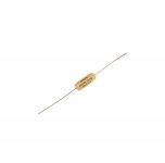
Would it be better to use non inductive resistors where Maouna has those cement wire wound resistors?
Would it be better to use non inductive resistors where Maouna has those cement wire wound resistors?
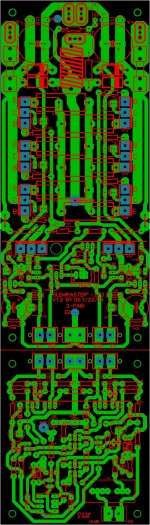
Here a combi of the 3Pair/NAD to save extra tooling cost
Attachments
Last edited:
Meanman,
Are you going to make this as a single piece board and then cut them or leave them as shown? Nice looking boards. Was the NAD one of the CFA or VFA designs?
Are you going to make this as a single piece board and then cut them or leave them as shown? Nice looking boards. Was the NAD one of the CFA or VFA designs?
Meanman,
Are you going to make this as a single piece board and then cut them or leave them as shown? Nice looking boards. Was the NAD one of the CFA or VFA designs?
That's OS his work not mine.CFA or VFA hope OS will answer that.
Normaly the're separate but to save money I made them on one board.You can cut it or not all up to you.
Finally, I can made my VSSA with Hawksford cascode sound "airy".
I change VAS current to 5-6 mA. Thanks, OS. 😎
I use 2SC3423Y and 2SA1360Y for VAS and pre-driver. The spice model from Keantoken, but I have strange result for slew rate simulation.
1: The square wave input is high by default for the Pulse source. For this reason the simulation starts as if the input voltage has been high rather than 0V.
2: The simulator gives me many errors. You are flying by the seat of your pants on getting the simulator to work and still getting usable results. I suggest you remove all signal sources and commands from the schematic, and then paste it into this file, replacing the opamp which is there to show you where the nodes go. This will get you a better signal generator and test platform.
http://startfetch.com/keantoken/ltspice/ampsim6.asc
Suggestions for improvements are welcome.
Last edited:
That's OS his work not mine.CFA or VFA hope OS will answer that.
Normaly the're separate but to save money I made them on one board.You can cut it or not all up to you.
I will combine nad-h /slewmaster, Closely spaced holes will be the "break point"
for the PCB. Will post later. 🙂
Edit - I read too fast ... you did do it. Add a bunch of holes across the "line" + make
sure the mounting holes are 6.35mm from the corners. ps - I see you made OP/interface pads
double sided-through hole ... excellent.
OS
Last edited:
OS,
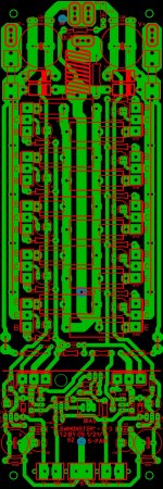
I's thinking wouldn't it be a good idea to take the 5 pair Slew-Master and people can decide themself if they build the 2 pair,3 pair are 5 pair amp?
OS can you send me your mail address?
I's thinking wouldn't it be a good idea to take the 5 pair Slew-Master and people can decide themself if they build the 2 pair,3 pair are 5 pair amp?
OS can you send me your mail address?
Last edited:

Would you create any problems if you did use the five pairs output boards and did not populate all of the output devices?
Also I never did see an answer to my question about using those cemented wire wound resistors on the boards and if the inductive nature of those would or could cause any problems? What happens when the inductive field is perpendicular to the traces as it would appear it would be in this application, or am I thinking to hard here?
Also I never did see an answer to my question about using those cemented wire wound resistors on the boards and if the inductive nature of those would or could cause any problems? What happens when the inductive field is perpendicular to the traces as it would appear it would be in this application, or am I thinking to hard here?
Ohmite does have nice induction free resistors,I did use them in my Blame ST
Those cemented wire wound are used very often in amps
Those cemented wire wound are used very often in amps
Attachments
Last edited:
Would you create any problems if you did use the five pairs output boards and did not populate all of the output devices?
Also I never did see an answer to my question about using those cemented wire wound resistors on the boards and if the inductive nature of those would or could cause any problems? What happens when the inductive field is perpendicular to the traces as it would appear it would be in this application, or am I thinking to hard here?
My opinion no problem.
OS posted a layout for the 5 pair output boards. I was looking for that post number, as their is not a direct reference.
Also I never did see an answer to my question about using those cemented wire wound resistors on the boards and if the inductive nature of those would or could cause any problems? What happens when the inductive field is perpendicular to the traces as it would appear it would be in this application, or am I thinking to hard here?
I sim 1uH series with 0.22 Ohm resistor. The inductor add small gain in high frequency and reduce phase margin (in my sim, it reduce from 77 degree to 46 degree). But I dont think the inductance is high as 1uH. Better use non inductive resistor.
Thanks meanman. I know that there are non inductive resistors and that was one of the reasons I was asking the question about the other type, if it causes any real problem in the application where they are being used or was I over-thinking this and just being an Audiofool?
I didn't think there would be any problem to not populating the output devices but again I was thinking that those extra traces could become RF antennae.
I didn't think there would be any problem to not populating the output devices but again I was thinking that those extra traces could become RF antennae.
OS posted a layout for the 5 pair output boards. I was looking for that post number, as their is not a direct reference.
Attachments
Bimo,
Thanks for the answer and for running the sims on that. You are much smarter here than I am, I am just learning.
Thanks for the answer and for running the sims on that. You are much smarter here than I am, I am just learning.
- Home
- Amplifiers
- Solid State
- Slewmaster - CFA vs. VFA "Rumble"