Can't figure why I made errors on the simple CFA-X 😕 .
Looked back to the VFA "wolverine" (paranoid 😱) no errors with a much
more involved layout.
The last "fixed" CFA-X I posted will work ..... but , it has to be "pretty".
(quick fix).
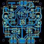
(Below) is the real purdey' CFA-X .
The reason I have reversed devices at the VAS (Q5/6) is so non-plastic
TO-126's will have the metal facing the heatsink and to preserve
the layout's symmetry (short paths from Q1/2 to Q5/6).
This amp is different with it's DUAL current feedback paths. "Float" the
main ground point with a resistor/inductor and those feedback pulses
"sour the milk" for the CCS/input pair. THD and stability suffer (amp
won't run with NO compensation anymore 🙁 ).
So .... separate, equal distance ground returns are the only option for
the CCS's and feedback returns (C5/R7-8 + C6/R9/10). Cancellation
will happen here .....The very "fat" trace and Lifted R3/D1-2 will ensure
none of this badness reaches the input filter/Q1-2 bases.
The same concept applies to output stage decoupling returns
or NFB take-off points .
A Simple circuit can have many more layout considerations than a
"bloated" one (wolverine). 😀
Again , many thanks to Mr. NICONOV !!
OS
Looked back to the VFA "wolverine" (paranoid 😱) no errors with a much
more involved layout.
The last "fixed" CFA-X I posted will work ..... but , it has to be "pretty".
(quick fix).
(Below) is the real purdey' CFA-X .
The reason I have reversed devices at the VAS (Q5/6) is so non-plastic
TO-126's will have the metal facing the heatsink and to preserve
the layout's symmetry (short paths from Q1/2 to Q5/6).
This amp is different with it's DUAL current feedback paths. "Float" the
main ground point with a resistor/inductor and those feedback pulses
"sour the milk" for the CCS/input pair. THD and stability suffer (amp
won't run with NO compensation anymore 🙁 ).
So .... separate, equal distance ground returns are the only option for
the CCS's and feedback returns (C5/R7-8 + C6/R9/10). Cancellation
will happen here .....The very "fat" trace and Lifted R3/D1-2 will ensure
none of this badness reaches the input filter/Q1-2 bases.
The same concept applies to output stage decoupling returns
or NFB take-off points .
A Simple circuit can have many more layout considerations than a
"bloated" one (wolverine). 😀
Again , many thanks to Mr. NICONOV !!
OS
Attachments
I will build seperates and try bridging. Bridging gives you voltage swing with lower rails and allows for higher bias as a result.
Group buy ...
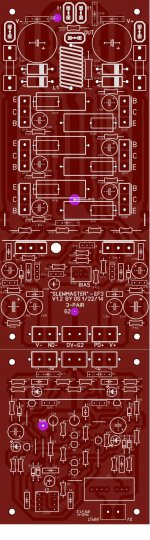
The already tested "slew" master 3- pair and the NAD (nx) -H has
been chosen !
I took the liberty to color the PCB red ... it looks superb.
Even as the NX is a good amp , it is "finicky" .... this IPS (nad-H)
can tolerate outright mismatches for input devices (servo).
Add the excellent Hawksford cascode and an EF3 ... it rules 😀 !!
This is a cool development , hope it comes through. 🙂
PS - NAF has been silent lately ... most likely re-listening to his whole music collection
on this setup.
OS
Attachments
Last edited:
Ostripper,
Is there a reason that you left this as two separate sections and did not create on single board? I see where the jumpers need to go, would there be any advantage to making this one piece?
I know the idea is to be able to change input sections, but if someone was only going to make this single design could anything be optimized with a single board? Does the CFA-X fit up the same way to the op board?
Ostripper,
Is there a reason that you left this as two separate sections and did not create on single board? I see where the jumpers need to go, would there be any advantage to making this one piece?
I know the idea is to be able to change input sections, but if someone was only going to make this single design could anything be optimized with a single board? Does the CFA-X fit up the same way to the op board?
This would even fit in a shallower case ... 8" (200mm) heatsink ...
IPS PCB is at a 90 degree angle to the OPS. This modular design has NONE
of the drawbacks. Distance from VAS to predrivers is short.
With the "floating NFB" and the "anal" layout ... these modules might
shame most of the other designs here on DIYA.

You could switch "CFA-X" with "NAD-H" without even a bias re-adjustment.
THAT's how standardized this is !! ALL IPS's are fully compatible with
ALL OPS's - 35v- 85 V power supplies,too. Ultimate options for E-waste PS's
and junkbox parts ... that how these are designed. 🙂
OS
So by putting the input section at 90 degrees to the output you are shortening rhe feedback wire, is that what I am understanding here? The feedback is still an externally routed wire from output to input? The is nothing on the input board that needs to be mounted to the heat-sink then or would it have some independent heat sinks mounted on any of the input transistors? How would you suggest to mount the ips section, on an angled bracket or sub aluminum plate attached to the main heat sink on an angle?
Hey OS, from an Inline output trannies in the Honey badger, you switched to a both sides of the pcb output trannies arrangement, any reason for the change?
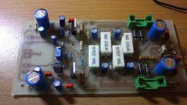
Finally, I can made my VSSA with Hawksford cascode sound "airy".
I change VAS current to 5-6 mA. Thanks, OS. 😎
I use 2SC3423Y and 2SA1360Y for VAS and pre-driver. The spice model from Keantoken, but I have strange result for slew rate simulation.
I change VAS current to 5-6 mA. Thanks, OS. 😎
I use 2SC3423Y and 2SA1360Y for VAS and pre-driver. The spice model from Keantoken, but I have strange result for slew rate simulation.
Attachments
Last edited:
Ostripper i am building the ''baby'' version with mjl21193-4.About output coil of 1.5uH,I am using 14 turns of 1.0 mm2 wire around a 12mm diammeter round object. is it ok or you have something else to suggest?is 1mm wire diammeter enough for 2 output pairs?
Finally, I can made my VSSA with Hawksford cascode sound "airy".
I change VAS current to 5-6 mA. Thanks, OS. 😎
I use 2SC3423Y and 2SA1360Y for VAS and pre-driver. The spice model from Keantoken, but I have strange result for slew rate simulation.
Hello Bimo ,
You have changed the VAS current to 5-6 ma from which value ?
Pay attention to the 4700uf capacitors from the feedback loop .At these big capacitors the equivalent series inductance is big(~100nHenry) therefore the resonant frequency is low < 20khz .It would be better to put across them a 100uf + 220nf .
Last edited:
Hello Bimo ,
You have changed the VAS current to 5-6 ma from which value ?
Pay attention to the 4700uf capacitors from the feedback loop .At these big capacitors the equivalent series inductance is big(~100nHenry) therefore the resonant frequency is low < 20khz .It would be better to put across them a 100uf + 220nf .
I change R26, R16, R255, R22.
In implementation, I bypass 4700uF with 100nF film cap.
I want to compare Hawksford cascode VAS with simple VAS and I want to build CFA with diamond buffer input (NX variant).
If you have OPS modul like this you want to try anything.....
I blame Ostripper because of this... 😀
So by putting the input section at 90 degrees to the output you are shortening rhe feedback wire, is that what I am understanding here? The feedback is still an externally routed wire from output to input? The is nothing on the input board that needs to be mounted to the heat-sink then or would it have some independent heat sinks mounted on any of the input transistors? How would you suggest to mount the ips section, on an angled bracket or sub aluminum plate attached to the main heat sink on an angle?
The input board could just be mounted with 2 standoff's at the rear
panel of the amp. Your input jack could be right next to it (a few CM's).
You can just use 25mm wire wrap terminals for the IPS interface
(no euroterminal) and tighten the OPS screws ... or untighten to
change the IPS.
A very shallow E-waste amp case (200-225mm) would be usable for the
Even the (9" 225mm) "monster" OPS. It could be used with a heatsink USA
250mm X 125mm extrusion.
IPS VAS devices have a small 75 X 25mm thin aluminum heatsink (I use
roof flashing - cut with scissors )...that's it (low current - COOL !)
OS
Last edited:
Hey OS, from an Inline output trannies in the Honey badger, you switched to a both sides of the pcb output trannies arrangement, any reason for the change?
"Badger" is an EF2 , (with a current gain 3-5k) it is more tolerant of longer
supply traces and driver/vbe feeds. Also, Jason and DIYA wanted it to
match the other store offerings (universal mountings).
The EF3 is another matter .. super short decoupling returns , driver/Vbe/
predriver section is compact and just CM's from the IPS input.
EF3 predriver bases are super hi-Z + gain is 50-100K !
So , notice the OPS input traces have 2cm+ "air" between them and
any other trace.
On the IPS collector outs (VAS out), the traces are running near
"clean" grounds. NO inductive pickup from "dirty" high current sources.
The separation of dirty/clean is my trademark .. from main PS to the
smallest signal transistors !! 😀
The "Badgers" power supply has the same super short (main)
grounding scheme and secondary decoupling for the small signal stages.
My receiver repair experience has shown me that just about ALL OEM
designs split the "dirty" supply (G1) from the "clean" (G2).
CFA amps are different , as I pointed out ... their current feedback returns
fall into the "dirty" category.
OS
What are the specs of the NAD-H with 5 pair OPS?
Very NICE work...Thanks
NAD-H + "slewmonster"
60-85V rails , 200-300W/8R ... 500W/4R (HK990/5 pair MJLxxxx specs - 72V rails).
40ppm THD20 full power / 6-20ppm 1/2 power.
1mv Offset ! (servo). 🙂
OS
Ostripper,
Could you post the basic power supply circuit for this combination of ips and ops for us. I don't think I want to look through the entire Honey Badger thread to see what you are recommending.
It seems that the difference in cost from a single output pair to say a triple would be very slight and would give loads of headroom in many applications. No worry about clipping on any transients and with a limit on the input side would guarantee a low distortion system as RNMarsh is so adamant about.
Hello Bimo ,
You have changed the VAS current to 5-6 ma from which value ?
Pay attention to the 4700uf capacitors from the feedback loop .At these big capacitors the equivalent series inductance is big(~100nHenry) therefore the resonant frequency is low < 20khz .It would be better to put across them a 100uf + 220nf .
The 4700uF resonance is a SERIES resonance. That means it's an inductor and cap in series and it has an impedance null, not a spike, and this is benign and unavoidable. You cannot do anything about an impedance null except add resistance in series - it already has 82R series resistance, which swamps the impedance null without a trace.
If you put any small cap across this one, the small cap will resonate with the large cap's series inductance. This will create a parallel resonator, which means an impedance spike that can disrupt the feedback loop and stability of the circuit.
Your solution will create a parallel resonator between the smallest cap and the inductance of the larger caps, and this is something that could worsen RF behavior and even cause instability, especially with such high feedback current.
It is also possible that the resonance could be positioned strategically to increase stability - but it is still a resonator, IE antenna.
Adding a 10u or 1u lytic cap should add enough damping to not cause problems, if you have small film caps in parallel with large caps.
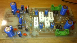
This is my progress so far.I have some questions. :
1)I have a pair of mjl21193-4 made by ON and a pair of mjl21193-4 made by Motorola.Can i mix/use them in the same channel?
2) Is 1mm wire enough for output coil?
3)I want to build a simple CFA topology . Which is the latest version of CFA-X input stage?
4)For C114 which curently is 0.68uF,I only have 0.47uF.Can i use it?
Attachments
Last edited:
Maouna,
I think post #701 is the latest CFA-X version OS has posted.
Is there any disadvantage to using the cemented wire wound resistors on the board, wouldn't those be considered inductive?
I think post #701 is the latest CFA-X version OS has posted.
Is there any disadvantage to using the cemented wire wound resistors on the board, wouldn't those be considered inductive?
-At .22 OP Re and 4.7R as basestoppers , the two dissimilar OP's might work ...This is my progress so far.I have some questions. :
1)I have a pair of mjl21193-4 made by ON and a pair of mjl21193-4 made by Motorola.Can i mix/use them in the same channel?
2) Is 1mm wire enough for output coil?
3)I want to build a simple CFA topology . Which is the latest version of CFA-X input stage?
4)For C114 which curently is 0.68uF,I only have 0.47uF.Can i use it?
Check right at the OP device emitters for (mV) when operational to ensure proper
current sharing.
-1mm OP inductor is good for the "baby" .
-0.47uF is fine for the "suckout" cap .... it
"pulls" the voltage back out of the capacitive OP junctions during switching.
BTW - nice ! precision drilling ... 63V caps ? 45-50v rails ?
OS
Last edited:
- Home
- Amplifiers
- Solid State
- Slewmaster - CFA vs. VFA "Rumble"