OS
Thanks for explenation. Another lesson taken.
Looks that I missed the one IPS, Eyesee look really nice and simple I must build it.
Please tell me which of all IPS boards is the fastest killer, I would like to solder something quick.
Thanks
Thanks for explenation. Another lesson taken.
Looks that I missed the one IPS, Eyesee look really nice and simple I must build it.
Please tell me which of all IPS boards is the fastest killer, I would like to solder something quick.
Thanks
If my scope tells anything the Krypton-C and Krypton-ND seem to be the fastest, thought the Eyesee doesn't seem too far behind.
I do not want to comment the final result. Those amps long gone, got dismantled and sold for fraction of the invested price
Good comment.
Today i manage to have another try to this IPS.
Installing an LM4562 instead of TL072 this IPS is more musical ,very good sounding!
Vas current must be modified ,it is double the recommendation OS ,please help.
Hi Thimios
I know you built several IPS, did you built the Spooky.
If yes how these compare sound wise to that.
Based on OS comment that was one of the best sounding IPS but that was before he designed these.
I do want to build at least one IPS and two or three OPS with transistors and fets both with Latfet and vertical to.
Thank you for your help here.
One more time if you built the Spooky I just want to know your opinion when you compare the two sound wise with out any responsibility knowing that we hear differently and sometimes we have different taste.🙂
Thank you!
Greetings
Today i manage to have another try to this IPS.
Installing an LM4562 instead of TL072 this IPS is more musical ,very good sounding!
Vas current must be modified ,it is double the recommendation OS ,please help.
Hi Thimios,
I had the same issue with the LM4562. If you look back at post 7159 your will see that OS suggested changing R6/8 to reduce the VAS current. I didn't try it yet. The OPA2134 works with the stock values.
Today i manage to have another try to this IPS.
Installing an LM4562 instead of TL072 this IPS is more musical ,very good sounding!
Vas current must be modified ,it is double the recommendation OS ,please help.
Increase R12 and 21 to 47-56R. Q3/5 -4/10 are current mirrors -
Ratio of those mirrors emitter resistors determines whether it is a
mirror (equal) , magnifier , or attenuator.
For example if R6 and 12 are 47R , 10ma that the IC draws will be
exactly copied on the main VAS emitter resistor (R12). But , the VAS
will have to share 2ma with the cascode LED string ... giving
8 ma leftover for the VASout.
OS
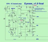
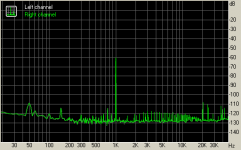
eyesee
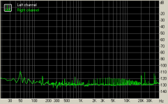
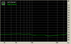
I think it's ok now🙄
I think it's ok now🙄
Attachments
-
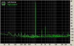 thd.png4.5 KB · Views: 174
 -
 noise.png4.3 KB · Views: 163
 -
 imdswept.png2.6 KB · Views: 175
 -
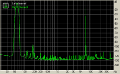 imd.png5.2 KB · Views: 476
 -
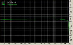 fr.png2.4 KB · Views: 491
 -
 dynamics.png4.2 KB · Views: 529
 -
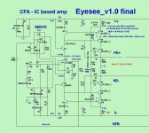 Eyesee-V1.0-schema MODIF.JPG93.8 KB · Views: 559
 -
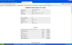 results.JPG111.4 KB · Views: 210
 -
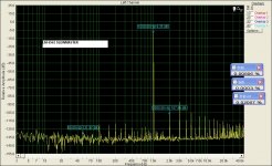 LM4562 SLEWMASTER 1.JPG365.6 KB · Views: 205
Last edited:
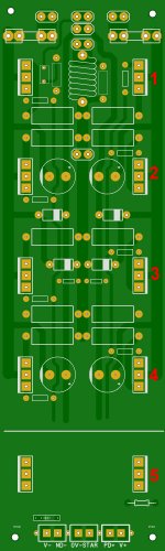
Does this look interesting to anybody? It's the EyeSee IPS with mosfet outputs.

There is nothing original here. I just swedged together the mini mosfet OPS and the EyeSee IPS into a common PCB. The PCB measures (roughly) 3 inches wide by 6.75 inches long. The mosfets could be double die and with +/-55 volts applied produce what?? 120 clean watts (more??) into an 8 ohm load.
There is nothing original here. I just swedged together the mini mosfet OPS and the EyeSee IPS into a common PCB. The PCB measures (roughly) 3 inches wide by 6.75 inches long. The mosfets could be double die and with +/-55 volts applied produce what?? 120 clean watts (more??) into an 8 ohm load.
Hi Thimios,
Thanks for pursuing this. I will have to make that change. The LM4562NA had the best looking square waves and made a big difference the A9 IPS. Can't wait to try it in the Eyesee now.
Blessings, Terry
Hi Carl,
That looks interesting. I have been using the mini lately for testing new IPS.
Thanks for pursuing this. I will have to make that change. The LM4562NA had the best looking square waves and made a big difference the A9 IPS. Can't wait to try it in the Eyesee now.
Blessings, Terry
Hi Carl,
That looks interesting. I have been using the mini lately for testing new IPS.
Last edited:
Carl,
It would be great if you could do the same with the Krypton-C. I would also like to hear if there would be much difference between the two in actual listening tests.
It would be great if you could do the same with the Krypton-C. I would also like to hear if there would be much difference between the two in actual listening tests.
Terry,
Did you use 8-pin sockets on any of your boards so you can change op-amps? Just wondering if you have to de-solder those from your boards.
Did you use 8-pin sockets on any of your boards so you can change op-amps? Just wondering if you have to de-solder those from your boards.
Does this look interesting to anybody? It's the EyeSee IPS with mosfet outputs.
There is nothing original here. I just swedged together the mini mosfet OPS and the EyeSee IPS into a common PCB. The PCB measures (roughly) 3 inches wide by 6.75 inches long. The mosfets could be double die and with +/-55 volts applied produce what?? 120 clean watts (more??) into an 8 ohm load.
Nice. I was thinking of doing a select few "all in one" creations.
OS
Carl,
It would be great if you could do the same with the Krypton-C. I would also like to hear if there would be much difference between the two in actual listening tests.
Easy enough to do. I'll take a swag at it and report back.
For all you board designers a question. Can you do one of these combination boards with both the input section and the output section and make it editable to adjust the number of output devices or do you have to redraw each time you make a change like that? Everything else being the same except for the number of outputs and the size of the board?
For all you board designers a question. Can you do one of these combination boards with both the input section and the output section and make it editable to adjust the number of output devices or do you have to redraw each time you make a change like that? Everything else being the same except for the number of outputs and the size of the board?
Yes like 1, 2,4 would be great
For all you board designers a question. Can you do one of these combination boards with both the input section and the output section and make it editable to adjust the number of output devices or do you have to redraw each time you make a change like that? Everything else being the same except for the number of outputs and the size of the board?
Jkeutmann Even made one with 6 outputs (pairs).
You can scale it up to 10 or more , just add emitter resistors , OP devices , and
basestoppers for each additional pair.
This is all "1st generation" art. Now that I am not sick and suffering 🙁 , time
to do the "better stuff".
(below) - a 5 pair. Just adding pairs at the close spacing of the original
slew output stages might be good for 2-3 pairs.
Bigger dissipation will need a 250-300mm 3U to 5U heatsink and every ounce
of aluminum matters here !!
With all 5 pairs spread across a 250mm PCB , each pair will have an equal area
of aluminum for dissipation. That is , each pair will see the same Celsius per watt and additionally would have the same thermal limits (failure , gain).
2 or 3 pairs on the attached layout would also be better thermally in positions
2/4 or 1/3/5.
PS - the previous slewmaster OPS is best using 3 pair , a 5 pair setup is
not ideal. Nothing will blow , but still not ideal.
OS
Attachments
OS,
I completely understand you concern with heat dissipation and spreading the output devices across the heatsink surface so you don't have devices to close together and causing localized high heat areas. I assume there is also the factor of the height and thickness of the fins on the heatsink and whether or not you use any kind of forced air cooling to help with the situation. I'll just use the 5 pairs boards I have to mount 3 pairs as you said. Whether I would ever need a 5 or 6 pair board is very questionable. I can usually design a set of speaker that with much less power would drive you out of the room before you could ever use that level of power. Now when I was doing PA and building bass horns that had dual 18" drivers that amount of power would be nice. Most of those amps were switch mode Class D type of power amps putting out over 1,000 watts per channel and banks of them. I'm not doing outdoor festivals so not needing to do that anymore. Still have molded parts to build 8 more bass horns, just not sure what I want to do with them.
ps. Sorry to hear you were sick and suffering, glad you are feeling better.
pps. I have one 24" bass driver that I have no specs on, came out of Mexico and looks like a clone of a JBL 18" scaled up to 24". Should make a nice sub-woofer if I ever test it and determine the T/S parameters.
Last edited:
Jkeutmann Even made one with 6 outputs (pairs).
You can scale it up to 10 or more , just add emitter resistors , OP devices , and
basestoppers for each additional pair.
This is all "1st generation" art. Now that I am not sick and suffering 🙁 , time
to do the "better stuff".
(below) - a 5 pair. Just adding pairs at the close spacing of the original
slew output stages might be good for 2-3 pairs.
Bigger dissipation will need a 250-300mm 3U to 5U heatsink and every ounce
of aluminum matters here !!
With all 5 pairs spread across a 250mm PCB , each pair will have an equal area
of aluminum for dissipation. That is , each pair will see the same Celsius per watt and additionally would have the same thermal limits (failure , gain).
2 or 3 pairs on the attached layout would also be better thermally in positions
2/4 or 1/3/5.
PS - the previous slewmaster OPS is best using 3 pair , a 5 pair setup is
not ideal. Nothing will blow , but still not ideal.
OS
Strange, I have 3 pair of the 5P OPS, one is VFET. None of them have exhibited any hint of a problem. I have run them for hours into 4 ohm speakers without problem. I do have them on pretty large heatsinks though. Maybe I just got lucky.
- Home
- Amplifiers
- Solid State
- Slewmaster - CFA vs. VFA "Rumble"