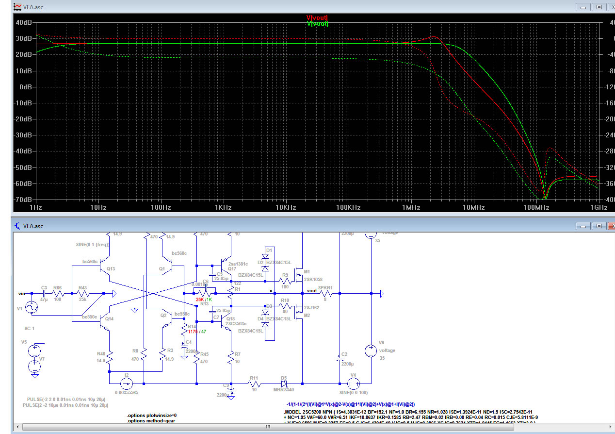
A question about the CFA vs VFA "competition":
As I read in a few posts there is a major difference in the bass region probably due to FB impedance issues.
If thats the case what about a VFA/CFA "converter" aka a FB buffer?
With a high input impedance input and a low output impedance output driving the input stage..?
I am sure thats also not a new idea so just asking... 🙂
A question about the CFA vs VFA "competition":
As I read in a few posts there is a major difference in the bass region probably due to FB impedance issues.
If thats the case what about a VFA/CFA "converter" aka a FB buffer?
With a high input impedance input and a low output impedance output driving the input stage..?
I am sure thats also not a new idea so just asking... 🙂
I think the whole controversy depends on your speakers. I haven't heard any difference in the bass with my system, but I've notice a substantial boost in higher frequency detail with CFAs. Especially at lower volume levels.
I've notice a substantial boost in higher frequency detail with CFAs. Especially at lower volume levels.
This is what I hear that is consistent about CFA topologies. IMO, from mid to upper-midrange on up is better.... a lot clearer - more detail.
But we havent nailed it down to what makes that distinction? SR? HF distortion? ???
THx-RNMarsh
This is what I hear that is consistent about CFA topologies. IMO, from mid to upper-midrange on up is better.... a lot clearer - more detail.
But we havent nailed it down to what makes that distinction? SR? HF distortion? ???
THx-RNMarsh
I've always notice my horns sounded better with higher voltage power supplies. My theory is CFAs are faster and able to deliver more voltage at higher frequencies, but I have no way to prove my theory.
A VERY bad idea. We don't want any distortion nor Poles and 0 in the feedbacks.If thats the case what about a VFA/CFA "converter" aka a FB buffer?
I would worsen the situation, solving nothing.
And there is no major issue: If you are looking for Speed (bandwidth and slew-rate), go for CFA. Else, go for LTP. With 30dB of closed loop gain, 10K in serial for the feedback of a VFA will only impact HF distortion by 10% and slightly reduce bandwidth.
Last edited:
I apologize guys I post the re-drawing of the Wolverine in post #7127 and I made mistake I forgot a connection from R2 to signal GND " a little bird" told me that 😛 , my bad, please if moderators have time delete post #7127 any away I just did it today in a couple of hour so is not gonna be "go" the fist time 😀
Regards
Juan
Regards
Juan
Attachments
Last edited:
Terry,
Wasn't that input section giving you oscillation problems when you first built it? Have you solved that problem or am I confusing that with another IP section? What happened with the Borys boards, did you fix that or are you waiting on Borys to test and solve that?
Wasn't that input section giving you oscillation problems when you first built it? Have you solved that problem or am I confusing that with another IP section? What happened with the Borys boards, did you fix that or are you waiting on Borys to test and solve that?
Hi Guys,
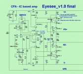
I built a new Eyesee IPS. It sounds pretty good but has low gain. Which resistor do I change to increase the gain?
Thanks, Terry
Eyesee ?? 🙄
R10 =
56R -26X
47R- 34X
33R- 42X (gain that is)
OS
A question about the CFA vs VFA "competition":
As I read in a few posts there is a major difference in the bass region probably due to FB impedance issues.
If thats the case what about a VFA/CFA "converter" aka a FB buffer?
With a high input impedance input and a low output impedance output driving the input stage..?
I am sure thats also not a new idea so just asking... 🙂
That would be the "infidel" IPS... one bad ar$e oscillator. Adding that extra
pole made this abomination oscillate in the FM band. (right on , esperado).
OS
Eyesee ?? 🙄
R10 =
56R -26X
47R- 34X
33R- 42X (gain that is)
OS
Great, I'll try that.
I didn't measure it but 56R sounds way lower than 26X
Terry,
Wasn't that input section giving you oscillation problems when you first built it? Have you solved that problem or am I confusing that with another IP section? What happened with the Borys boards, did you fix that or are you waiting on Borys to test and solve that?
Hi Kind,
No, it played OK but was uninspiring. I have since bought some more expensive ICs to try out. The first one I built was on poor quality boards so I etched some new ones. I'll report back after I've raised the gain so they will compare better to my other amps.
I etched and populated the new layout for Borys' OPS but it has issues so I need to troubleshoot it. I put it aside for a few days to clear my head. I built the mini Slew OPS and finished Valery's ALLFET IPS in the meantime.
Blessings, Terry
Last edited:
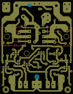
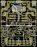
Hello.I made a single pair output stage based mostly on Ostripper's layout. I cant tell if layout meets all proper rules for good stability and performance.I would be gratefull if anyone is interested in giving it a try and test it with an oscilloscope. it is about 10mm x 7.9mm.for the time being i run out of parts.. Here are all the files needed:
Attachments

Eyesee ?? 🙄
R10 =
56R -26X
47R- 34X
33R- 42X (gain that is)
OS
I changed R10 to 33R. I suppose I must have something else wrong because I only have 10X gain. 1Vac input = 10Vac output.
Tomorrow I will get out my first pair and test those to see I have the same thing.
OK I found the issue with the gain. When I started populating the boards I transferred the values from the schematic to the silk screen printout to make things easier. When doing that I marked R15 and R16 as 680 instead of 680k. I discovered this when I tested the original boards I had done and saw that they had good gain. Comparing the two helped me discover it. So now the gain is good with original value tor R10. However, the VAS has too much output. The pot has no affect. I installed 1R resistors between the IPS and OPS and measure 12mV across those resistors so I assume 12mA when it should be 4.5-5.5mA. Any ideas?
Thanks, Terry
Thanks, Terry
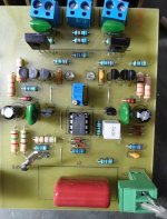
Terry can you post a photo.If i well remember i have an easy somewhere...OK I found the issue with the gain. When I started populating the boards I transferred the values from the schematic to the silk screen printout to make things easier. When doing that I marked R15 and R16 as 680 instead of 680k. I discovered this when I tested the original boards I had done and saw that they had good gain. Comparing the two helped me discover it. So now the gain is good with original value tor R10. However, the VAS has too much output. The pot has no affect. I installed 1R resistors between the IPS and OPS and measure 12mV across those resistors so I assume 12mA when it should be 4.5-5.5mA. Any ideas?
Thanks, Terry
Terry can you post a photo.If i well remember i have an easy somewhere...
Sure.
Attachments
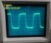
I hope you guys don't mind me taking you along on my journeys. I found the issue with the VAS current. I was kind of under the impression that this IPS would allow substitutions of ICs. Well I guess this isn't the case, at least not with some value changes. I have a few different dual op amps so my plan was to try different ones so see if I could detect any audible differences as well as see something on the scope. I initially had a TL072P in them but when the gain was so low I substituted an LM4562. Once I fixed the 680K resistor debacle, I left those in there. After thinking about it for a while I decided to reinstall the TL072Ps and now the VAS current is at 4.7mA which is where is is supposed to be. So I'm thinking, the other op amps might work with some value changes but not the way I have it set up. I also tried the NE5532P. That one sets the current to about 9mA. The square waves look a little better with the NE5532P and LM4562 but that might be because of the higher VAS current, I'm not sure. I also tried the OPA2134P which looks and acts just like the Tl072P. I'm attaching some scope pics of the NE5532P.
I take back what I said about this IPS earlier. It sounds very good.
Blessings, Terry
I take back what I said about this IPS earlier. It sounds very good.
Blessings, Terry
Attachments
-
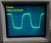 EYESEE 100khz 5532.jpg45.1 KB · Views: 145
 -
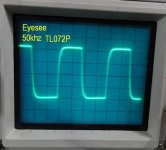 EYESEE 50khz.jpg49.1 KB · Views: 137
 -
 EYESEE 50khz 5532.jpg47.7 KB · Views: 132
 -
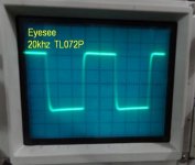 EYESEE 20khz.jpg43.4 KB · Views: 134
 -
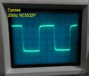 EYESEE 20khz 5532.jpg44 KB · Views: 133
 -
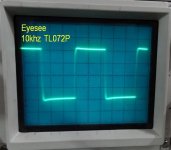 EYESEE 10khz.jpg48.1 KB · Views: 137
 -
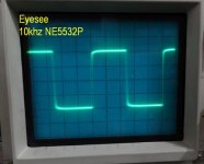 EYESEE 10khz 5532.jpg44.5 KB · Views: 132
 -
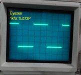 EYESEE 1khz.jpg49 KB · Views: 129
 -
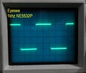 EYESEE 1khz 5532.jpg43.9 KB · Views: 479
 -
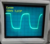 EYESEE 100khz.jpg46.6 KB · Views: 146
I hope you guys don't mind me taking you along on my journeys. I found the issue with the VAS current. I was kind of under the impression that this IPS would allow substitutions of ICs. Well I guess this isn't the case, at least not with some value changes. I have a few different dual op amps so my plan was to try different ones so see if I could detect any audible differences as well as see something on the scope. I initially had a TL072P in them but when the gain was so low I substituted an LM4562. Once I fixed the 680K resistor debacle, I left those in there. After thinking about it for a while I decided to reinstall the TL072Ps and now the VAS current is at 4.7mA which is where is is supposed to be. So I'm thinking, the other op amps might work with some value changes but not the way I have it set up. I also tried the NE5532P. That one sets the current to about 9mA. The square waves look a little better with the NE5532P and LM4562 but that might be because of the higher VAS current, I'm not sure. I also tried the OPA2134P which looks and acts just like the Tl072P. I'm attaching some scope pics of the NE5532P.
I take back what I said about this IPS earlier. It sounds very good.
Blessings, Terry
Do you have the original Eyesee schema ? I made a verbose series of comments regarding this.
"Current ratio R6/12 and R8/21
are dependent on U1 total current."
"R6/8 = 39-47R for TL072"
"R18 - Vbias fine tunes VAS after ratio is set."
The V/I converter is the IC , it's idle current determines the
VAS current mirror bias. The current mirror can be scaled to ratio
as explained on the schematic.
That ratio is R6 over R12 and R8 over R21 - directly. Running the op-amp
on a test board (alone) at +/-12V would determine IC current ... datasheets
will also tell you this.
I could of just specified the use of one IC , but what fun would that be ?
Glad you got it. OBEY the schema - it can be "fine tuned" 😀 .
Edit - 100R = R6/8 for the 5532 .... should give about @ 5ma VAS !
OS
Last edited:
Do you have the original Eyesee schema ? I made a verbose series of comments regarding this.
The V/I converter is the IC , it's idle current determines the
VAS current mirror bias. The current mirror can be scaled to ratio
as explained on the schematic.
That ratio is R6 over R12 and R8 over R21 - directly. Running the op-amp
on a test board (alone) at +/-12V would determine IC current ... datasheets
will also tell you this.
I could of just specified the use of one IC , but what fun would that be ?
Glad you got it. OBEY the schema - it can be "fine tuned" 😀 .
Edit - 100R = R6/8 for the 5532 .... should give about @ 5ma VAS !
OS
Hi Pete,
I saw the note on the schematic but didn't know how to work out the math. Still don't if that matters. I might try raising R6/8 to see if that helps the 5532. It will be interesting to see if the 5532 still looks better than the TL072 once it is running at the same current. I guess if I want to run the LM4562 R6/8 might need to go even higher.
I forgot to mention, even using the TL072, the pot has very little affect.
Thanks again, Terry
Last edited:
- Home
- Amplifiers
- Solid State
- Slewmaster - CFA vs. VFA "Rumble"