Hi Pete,
I saw the note on the schematic but didn't know how to work out the math. Still don't if that matters. I might try raising R6/8 to see if that helps the 5532. It will be interesting to see if the 5532 still looks better than the TL072 once it is running at the same current. I guess if I want to run the LM4562 R6/8 might need to go even higher.
I forgot to mention, even using the TL072, the pot has very little affect.
Thanks again, Terry
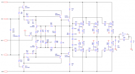
If you are measuring R12/21 (only) to determine VAS I ... you won't see nutin ' !
All these cascoded LED wonders are measured by the total VAS current
MINUS the LED cascode reference current.
An example would be the voltage drop across R21 MINUS the voltage drop
across R17 (converted to I).
As you turn the trimmer , R17's Vdrop would change ... as more or less
current flowed through the LED's.
Edit - I forgot this initially .... To get a real 5-6ma at VAS out , R12/21 would most
likely be at 7-8ma I. (1.5-2ma for the LED's).
OS
Last edited:
If you are measuring R12/21 (only) to determine VAS I ... you won't see nutin ' !
All these cascoded LED wonders are measured by the total VAS current
MINUS the LED cascode reference current.
An example would be the voltage drop across R21 MINUS the voltage drop
across R17 (converted to I).
As you turn the trimmer , R17's Vdrop would change ... as more or less
current flowed through the LED's.
Edit - I forgot this initially .... To get a real 5-6ma at VAS out , R12/21 would most
likely be at 7-8ma I. (1.5-2ma for the LED's).
OS
Hi Pete,
I will use that method to double check. The method I used was to insert 1R/5W resistors between PD/PD and ND/ND and measuring the voltage drop. I'm not sure how you measure Slew rate but this IPS has some pretty good looking square waves and it sounds very good.
Thanks, Terry
Cortez,
I agree. If you want to add some links and commentary to the wiki that way
people don't get lost through pages and pages and pages and pages of stuff.
To OS' credit he is using the first page as a guide. That's pretty good.
Anyway here is the wiki link:
wiki link: Slewmaster Resources
So I finally gave up trying to figure out what to build and figured I'd
start rebuilding my old McIntosh MC250. It is all in one place at least
it was at the start.
Now, I'm trying to figure out which transistors are fried and try to find
replacements. ; ( w/o, ruining some nice heat sinks. Heck, I'd have to send them
to Terry so he can anodize or paint them.
BTW Terry, nice work there getting all those Scope Test pics up. 🙂
and finding problems too. That honey badger is starting to look
pretty good.
I guess I'm getting too old to work on little stuff...then again, when I try my hand
at big stuff, that is hard to do too....but that old '69 SS396 Chevelle, she just keeps calling my name
and wants to drive...in spite of her problems minor as they may be. I just have to install a baby
seat in it and go...as long as it doesn't rain nor run out of gas (you can see the gauge getting
lower as you drive).
Last edited:
Where is the BOM for the 5P Slewmaster?
Unfortunately , the BOM is the schematic.
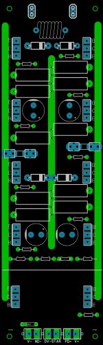
I'm working on a universal IRFP/MT-200/TO-3p-264 5P slewmaster now.
The present one is alright , but ......
- Has the devices too close together (not thermally "ideal")
-Can't do the HEXFET's
-Loop area can be reduced further/grounding can also be improved.
-Main rail feeds in the middle (less inductance).
-Just 2 pair 470u-680u decoupling in a symmetric pattern.
The present 5P's I have are good with TO-3P's , Still4givens 264's with
the larger heatsinks are most likely OK , also.
On my amp , the center pair outputs are 1mv higher bias than the others.
My 3 pair MT-200's amp - does not do this !
Thermally "Spreading out" the 5 pairs on a 250mm PCB , relocating the
main output Vbe close to the one device on the 1'st pair. (below)
The present 5P's - I would recommend 3 pair MT-200 in the pair 1/3/5
positions , that is ... with a smaller 3U heatsink.
PS - have to redraw all the sprint 6 artwork to use sprint 5 again. Both
versions of 6 I've used have crashed. Since I have to do this , my "nex-gen"
artwork will be stunning.
150W to 600W will be the range of this new addition.
OS
Attachments
Then where is the schematic? I thought it would be in the first post but it isn't. I understand what you are doing OS, now you can run 5P of MT-200. Those devices are $6.38 each at Digikey.
Hi
I read your post about IRFP (mosfet) I would like to take the courage to ask about a bit different version of mosfet (based on the Corddel) circuit.
I do have some of these Toshiba mosfets, I would like to (put then to good use) use them in a working circuit.😀
I'm ready to fabricate the PC boards but before that it would be god to get a second opinion from a pro like you OS or Jason and others before I do so.
Thank you very much.🙂
Greetings
Attachments
Hi
I read your post about IRFP (mosfet) I would like to take the courage to ask about a bit different version of mosfet (based on the Corddel) circuit.
I do have some of these Toshiba mosfets, I would like to (put then to good use) use them in a working circuit.😀
I'm ready to fabricate the PC boards but before that it would be god to get a second opinion from a pro like you OS or Jason and others before I do so.
Thank you very much.🙂
Greetings
You can try this working circuit with IRFP VMOSFET, but it does not use an EC. http://www.diyaudio.com/forums/solid-state/243481-200w-mosfet-cfa-amp-77.html#post4307021.
Then where is the schematic? I thought it would be in the first post but it isn't. I understand what you are doing OS, now you can run 5P of MT-200. Those devices are $6.38 each at Digikey.
-each post ,(#500,502,504) has the unified 2p/3p/5p schema in the
attached zip file. First post lists these posts ....
More than just the MT-200's , I'll see how to make the IPS plug in "inverted"
above the OPS , and have just the 76 X 250mm footprint.
(Vzaichenko's molex connectors ... maybe)
I want Pass Labs X250/350 power and professionalism. The slews work so
good , why not go to the next level ?
OS
You can try this working circuit with IRFP VMOSFET, but it does not use an EC. http://www.diyaudio.com/forums/solid-state/243481-200w-mosfet-cfa-amp-77.html#post4307021.
You are welcome to suggest any LFET amp.
I DO NOT plan to support
Lfets. Vfet's + BJT's are the easiest to source and offer the same SQ.
Vzaichenko uses my vfet IRFP OPS to "abuse" with his new creations ... I
trust it will be reliable with the new OPS.
OS
gaborbella
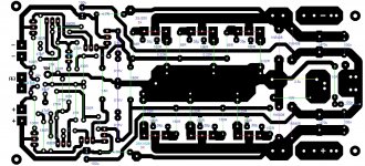
In my opinion (and tested on prototypes too) the better way is to split the OP transistors emitter/source return (as in slewmaster board) and join them at the single point (where NFB is taken) than put one big pad in the center. For the mosfets you do not need extra predriver, one driver pair will be good enough. Take a closer look at the sony's amp using same toshiba mosfets I think you can adopt their thermal compensation (they tested it for sure).
OS
I have made the board with big single track joining all emiter resistors like in post 7165 and I have done some measurements on real animal (as acurate as I could) and better performance was shown by the board like genuine slewmaster type (separate returns from emitter resistors, joined in one point). I have went further and make a board with two layers (in slevmaster builds thread) with supply in the center (top and bottom) and the performance improved a bit further.
I have no idea if I am right or wrong but I have learned it making a prototypes and reading two nice well known books 😀
I the heavy current tracks can be run in the way so the all electromagnetic-field can be reduced to minimum.
the heavy current tracks can be run in the way so the all electromagnetic-field can be reduced to minimum
At least for the rail tracks , If you can supply them from a mid point and
get a double sided Imax of 30A+ , Inductance will drop to the sub- uH range.
There is enough room for the output track to make it 30A+. here it
doesn't matter , as you already have inductance at the output L/C.
It's the returns from the decoupling caps that need to be away from
any sensitive sections ... plus be as short as possible. Ground is "king"!
OS
You can try this working circuit with IRFP VMOSFET, but it does not use an EC. http://www.diyaudio.com/forums/solid-state/243481-200w-mosfet-cfa-amp-77.html#post4307021.
Because Toshiba mosfets are better quality. They were made for audio.
Also I already have them, they were not cheap so basically I want to put them to good use.
I built several Pass mplifier with IRFP mosfet, I do not want to comment the final result. Those amps long gone, got dismantled and sold for fraction of the invested price.
Greetings
gaborbella
In my opinion (and tested on prototypes too) the better way is to split the OP transistors emitter/source return (as in slewmaster board) and join them at the single point (where NFB is taken) than put one big pad in the center. For the mosfets you do not need extra predriver, one driver pair will be good enough. Take a closer look at the sony's amp using same toshiba mosfets I think you can adopt their thermal compensation (they tested it for sure).
Thank you Borys🙂
Where can I get some info about the sony's amp please let me know
Greetings
You are welcome to suggest any LFET amp.
I DO NOT plan to support
Lfets. Vfet's + BJT's are the easiest to source and offer the same SQ.
Vzaichenko uses my vfet IRFP OPS to "abuse" with his new creations ... I
trust it will be reliable with the new OPS.
OS
Oh sorry, I trespass your territory, I promise I'll do it no more.
Oh sorry, I trespass your territory, I promise I'll do it no more.
No , I'm more mature than that. Let them build as they please.
But I hold as a rule to not inject my projects into another project thread ..
unless (like Vzaichenko's IPS's), they would relate to my project.
Or , some design specific.... (an example) is worthy of it.
Just an unwritten professional courtesy. 🙂
OS
OS
What type of output devices do the X250 and X350 use? From the pictures I saw on the internet of the internals both use many output devices. Do you have a number of output devices you are shooting for? I hope what ever direction you head will include a HEC of sorts.😀
What type of output devices do the X250 and X350 use? From the pictures I saw on the internet of the internals both use many output devices. Do you have a number of output devices you are shooting for? I hope what ever direction
you head will include a HEC of sorts.😀OS
What type of output devices do the X250 and X350 use? From the pictures I saw on the internet of the internals both use many output devices. Do you have a number of output devices you are shooting for? I hope what ever direction
5 pair mt-200 , IRFP's , or semelab BJT's would get you in the X250 range.
the semelabs might be like 7+ IRFP's (almost X350 territory).
The X250 uses 6 pair IRFP240/9240 - latest Project - 220 WPC Amp - Page 2.
As far as a HEC , I don't know .... what I'm now listening to now "smokes" a
parasound or H/k ... Do I need a HEC ... ??
OS
- Home
- Amplifiers
- Solid State
- Slewmaster - CFA vs. VFA "Rumble"