Strange, I have 3 pair of the 5P OPS, one is VFET. None of them have exhibited any hint of a problem. I have run them for hours into 4 ohm speakers without problem. I do have them on pretty large heatsinks though. Maybe I just got lucky.
I'm sure there is no real issue. At this point it looks like ostripper is in more of an 'optimization' mode now. Just taking the lessons learned and taking the next steps, a natural evolution so to speak.
Strange, I have 3 pair of the 5P OPS, one is VFET. None of them have exhibited any hint of a problem. I have run them for hours into 4 ohm speakers without problem. I do have them on pretty large heatsinks though. Maybe I just got lucky.
When I tested mine they played fine and seemed to work great but if I measured the temperature on the output devices the center one would be noticeably warmer and the bias current would be higher than the outside pairs. This was when running them into a 4 ohm dummy load. Even with my 3 pair MT-200s the center devices run warmer but not as extreme. Larger heatsinks may help.
I can see that but dangerously hot or just warmer? It might be impossible to get it so that the end transistor don't run somewhat cooler since they adjacent to an open area of heatsink. I suppose you might be able to raise the bias on the end units to make them more in line with the rest. I would imaging this happens with all amps that have a line array of devices.
Has anyone ever used a thermocouple to drive a circuit to modulate the bias current of the output devices, is this even possible? And has anyone actually measured the operating temperature of one of the 5 pairs boards to confirm that they stay within the SOA of the devices over time?
I can see that but dangerously hot or just warmer? It might be impossible to get it so that the end transistor don't run somewhat cooler since they adjacent to an open area of heatsink. I suppose you might be able to raise the bias on the end units to make them more in line with the rest. I would imaging this happens with all amps that have a line array of devices.
I wouldn't say it's dangerously warmer but it's hard for thermal compensation to work properly if this is happening. Other than the slight delay for initial warm-up, thermal compensation is perfect on these through the whole temperature range I tested with MJE340 for Q103/104.
it is not a good idea, on a thermal point of view to arrange output devices one near the other on the board.I would imaging this happens with all amps that have a line array of devices.
Unless the cooler have a very large thickness of conductive base.
I have been attaching the vbe to the top of one of the end outputs. On my boards the bias always reduces slightly when the amp becomes fully warmed up. I suppose that is considered over compensated. My question is, can your really hear any difference between 100mA bias and 90mA bias? I can't. Mine stays steady. I usually set the bias measuring across a pair of the inner emitter resistors.
it is not a good idea, on a thermal point of view to arrange output devices one near the other on the board.
Unless the cooler have a very large thickness of conductive base.
So how do you avoid this? Place them in a circle?
I assume you can calculate the minimum necessary distance apart for the output devices as long as you know the thermal dissipation of the heatsink you are using. I think what Esperado is saying is that we should not mount the devices close together just to make the board shorter but should spread the output devices so they are equally spaced across the heatsink's length.
OS,
I completely understand you concern with heat dissipation and spreading the output devices across the heatsink surface so you don't have devices to close together and causing localized high heat areas. I assume there is also the factor of the height and thickness of the fins on the heatsink and whether or not you use any kind of forced air cooling to help with the situation. I'll just use the 5 pairs boards I have to mount 3 pairs as you said. Whether I would ever need a 5 or 6 pair board is very questionable. I can usually design a set of speaker that with much less power would drive you out of the room before you could ever use that level of power. Now when I was doing PA and building bass horns that had dual 18" drivers that amount of power would be nice. Most of those amps were switch mode Class D type of power amps putting out over 1,000 watts per channel and banks of them. I'm not doing outdoor festivals so not needing to do that anymore. Still have molded parts to build 8 more bass horns, just not sure what I want to do with them.
ps. Sorry to hear you were sick and suffering, glad you are feeling better.
pps. I have one 24" bass driver that I have no specs on, came out of Mexico and looks like a clone of a JBL 18" scaled up to 24". Should make a nice sub-woofer if I ever test it and determine the T/S parameters.
Thank you ... I feel SO much better.
 Did not want to build , design (or even
wake up for almost a month).
As I explained , even 2 pair would be better at distance. Still4given , yes ..
I said your 5U "monster sinks" would not be affected much by this errata.
The "monster sinks" draw heat out in all 4 directions , a 3U will just dissipate
horizontally , making the center pairs hotter.
The other additions I will make.
-IRFP with zener protection capable.
-1-2Kuf on-board decoupling.
-miniaturize the capacitance multipliers
with indicators for the multipliers (red LEDS).
I might make a darlington multiplier. Then I can use
a much smaller cap with 100X the active device Beta.
OS
It is a pretty boring procedure to achieve a balanced temperature of several output devices on a given heat sink profile. But one thing is sure, we, have, ideally, to make this done before to design the PCB, if the output devices are directly on it. The relative spaces between them can change a lot depending of the chosen profile and the way they are mounted in the amplifier enclosure.So how do you avoid this? Place them in a circle?
Last edited:
Has anyone ever used a thermocouple to drive a circuit to modulate the bias current of the output devices, is this even possible? And has anyone actually measured the operating temperature of one of the 5 pairs boards to confirm that they stay within the SOA of the devices over time?
Everything is well below SOA and device thermal limits. I am just optimizing
for ALL heatsinks (3U/4U/5U) and even the event of a full 5 pair MT-200
OPS.
I measured mine ,when real hot .....
46 50 52C (outer to middle), out at the ends of the heatsink are only <40C.
This tells me I could drop all my devices temperatures by almost 8-10C with
a better distribution.
This turns into a spread of 12-15mv on those emitter resistors.
That means my bias is 55-70ma from out to inner. The Vbe is
sensing the average heatsink thermal , so setting the second pair's
Vbe is the most accurate. If that pair is 13.5mv , my whole OPS is
averaging 60-65ma.
Still4given ... the Vbe out on leads should also go to either second pair
in from the end. That pairs resistor should also be the one measured to
set bias. PS - also DO NOT WORRY .... your sinks nearly eliminate this "issue".
You could test all your Re's for me ... thanks.
OS
Last edited:
Terry,
I received your package today. Now I feel bad that you sent it overnight, that cost almost as much as I sent you!
Thank you,
Steven
I received your package today. Now I feel bad that you sent it overnight, that cost almost as much as I sent you!
Thank you,
Steven
No, just priority mail. It got to you overnight because we only live 90 miles from each other. I hope you get a chance to build them. It is very potent for such a small package.
Terry,
I will build this and use it with the Krypton-C boards I also have now. Could one of these boards be used with one of the double die output devices? Just wondering after the resent posting the last few days.
I will build this and use it with the Krypton-C boards I also have now. Could one of these boards be used with one of the double die output devices? Just wondering after the resent posting the last few days.
Hi Steven
I just plugged in a MJL4281 and it fits fine. The mounting hole may need to be enlarged slightly. I don't have a double die device but unless they are much larger than the big BJTs they should fit fine. At any rate, the most that would be needed would be to add a new hole to fit the mounting hole through. On my boards, I use an old/bad BD139 as a spacer between the board and the top of the mosfet so I can cinch the bolt down and now worry about the device heating up the board.
Blessings, Terry
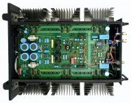
Well, in some cases of high-power reference designs, each output pair is mounted on the separate heatsink section.
This is Lamm M1.2. One channel. No compromise 😉
That looks like a LFET OPS. Here , you can do this (separate heatsinks) ..
negative thermal co-efficient. Unless they couple those heatsinks -
still I see NO Vbe and it is not ideal.
On a class A or AB BJT OPS , if one pair had more beta , it would become
hottest - "hog" the current and runaway ... poof !!
Did this on my first Badger prototype (caught it before "poof" !! 😀 ).
Our very own Nelson Pass has the best output stage idea (below).
Those X class OPS's are A/AB and do 2R loads (at 700W).
New Slew will be at the "Pass" level. He uses a flat ribbon to run
a separate IPS/OPS , too.
Nothing but the BEST !
OS
Attachments
I like this way ,come on OS make a layout like this.🙂That looks like a LFET OPS. Here , you can do this (separate heatsinks) ..
negative thermal co-efficient. Unless they couple those heatsinks -
still I see NO Vbe and it is not ideal.
On a class A or AB BJT OPS , if one pair had more beta , it would become
hottest - "hog" the current and runaway ... poof !!
Did this on my first Badger prototype (caught it before "poof" !! 😀 ).
Our very own Nelson Pass has the best output stage idea (below).
Those X class OPS's are A/AB and do 2R loads (at 700W).
New Slew will be at the "Pass" level. He uses a flat ribbon to run
a separate IPS/OPS , too.
Nothing but the BEST !
OS
- Home
- Amplifiers
- Solid State
- Slewmaster - CFA vs. VFA "Rumble"