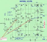
First, assemble your amp as it is, and find the good miller value for having a flat bandwidth as high as possible with no peak in the response curve. If you can, try to set the miller between the output of the amp and the base of the VAS, (C5,C7 in my schematic) as it reduce distortion because the output stage has a high current capability.Well, is this your suggestion?
Then, add a base stopper(R14/R15 in my schematic) +cap (C11,C12) to the second transistor in order to just kill any overshoot with low level 100KHz square waves. Verify with high level square waves (fast). The value of this base stopper resistance has to be calculated to do not charge the first transistor out of his range.
Then you will like to add an other low pass filter (R66, C3) to the input to ensure no signal will never reach the slew rate of the amp. I find the perfect value of this last filter in listening, cause it depends a lot on your system.
Hoping i'm clear ?
Last edited:
If i well understand...First, assemble your amp as it is, and find the good miller value for having a flat bandwidth as high as possible with no peak in the response curve. If you can, try to set the miller between the output of the amp and the base of the VAS, (C5,C7 in my schematic) as it reduce distortion because the output stage has a high current capability.
Then, add a base stopper(R14/R15 in my schematic) +cap (C11,C12) to the second transistor in order to just kill any overshoot with low level 100KHz square waves. Verify with high level square waves (fast). The value of this base stopper resistance has to be calculated to do not charge the first transistor out of his range.
Then you will like to add an other low pass filter (R66, C3) to the input to ensure no signal will never reach the slew rate of the amp. I find the perfect value of this last filter in listening, cause it depends a lot on your system.
Hoping i'm clear ?
Attachments
Last edited:
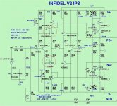
No the basestoppers-capacitors goes on Q-5 an Q-7, more in doubt on the backside pair, as you need all the speed you can get here, if the the need any BW reduction it should be less than on the front side.
Ok thanks i will try this tomorrow🙂No the basestoppers-capacitors goes on Q-5 an Q-7, more in doubt on the backside pair, as you need all the speed you can get here, if the the need any BW reduction it should be less than on the front side.
Attachments
Last edited:
Ok. You can try 100 Ohms for the resistances. Now, You'll have a problem with the other side (inverting) of the LTP. Here, you need the less phase turn you can achieve in order to keep a good feedback at HF. (Reason why i prefer Current feedback topology). You could try in a first attempt to add the same 100 Ohm, but without the capacitances. But you will face with the non linearity of the parasitic capacitance of Q6 and Q8. And i have no idea of the impact on distortion at HF. May-be you can try to add a little capacitance in // with the feedback path in order to compensate this phase turn in the feedback as much as possible.Ok thanks i will try this tomorrow🙂
AS it can be a long run to optimize, i would play with simulation before trying-all this on real.
To be sincere, i think this amp will be the hell to optimize. By example, i don't like the C7,C8 positions on the Q12,Q13 collectors, charging them at HF.
Courage 🙂
On my side, i'm just back from the hospital after an myocardial infarction, quite tired, and will not be of a great help for some days, as i feel myself like a 0% yogurt.
Last edited:
Thanks Esperado i wish you the best with your health!Ok. You can try 100 Ohms for the resistances. Now, You'll have a problem with the other side (inverting) of the LTP. Here, you need the less phase turn you can achieve in order to keep a good feedback at HF. (Reason why i prefer Current feedback topology). You could try in a first attempt to add the same 100 Ohm, but without the capacitances. But you will face with the non linearity of the parasitic capacitance of Q6 and Q8. And i have no idea of the impact on distortion at HF. May-be you can try to add a little capacitance in // with the feedback path in order to compensate this phase turn in the feedback as much as possible.
AS it can be a long run to optimize, i would play with simulation before trying-all this on real.
To be sincere, i think this amp will be the hell to optimize. By example, i don't like the C7,C8 positions on the Q12,Q13 collectors, charging them at HF.
Courage 🙂
On my side, i'm just back from the hospital after an myocardial infarction, quite tired, and will not be of a great help for some days, as i feel myself like a 0% yogurt.
Best regards.
Thimios.
Take care of yourself and get well my friend. This thread isn't going away soon so take your time and feel better. Not sure what 0% yogurt would taste or look like, but it doesn't sound to appetizing!
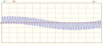
I don't seem to be winning with my Slewmonster stereo. Now I'm getting a 2MHz oscillation as soon as I turn the bias up. It doesn't seem to matter what input board I have connected or if the input is shorted. Any ideas where to start?
WOW !I don't seem to be winning with my Slewmonster stereo. Now I'm getting a 2MHz oscillation as soon as I turn the bias up. It doesn't seem to matter what input board I have connected or if the input is shorted. Any ideas where to start?
That's hard to believe ??
Pictures ... bottom of board - top of board.
Choice of pre/driver/output - I have 3 combo's working ...
mje340/350 - 2sc3263/2sa1294 - car stereo outputs c4388/a1673
c3505/a1381 - 2sc3263/2sa1294 - Sanken mt-200 c3264/a1295
No cap multiplier on this one , just 220u/.1u at PD+/ND-
c3503/a1381 - 2sc3263/2sa1294 - 5 pair ON semi NJW0281/0302.
Likely candidates - C107/C109 ( predriver shunts) edit - the 2 33pf's
predriver/driver R/C ... C111/113 and R114/115 (10R 2w + 22uF)
Make sure you have G2 hooked under board !!!
I've even hooked up IPS's with backwards/missing parts and not fried these.
When working properly- PERFECT thermal /electrical/ sound performance.
(I have not built in 4 years - all these were SO easy)
Show those pic's / specify those parts...
OS
Last edited:
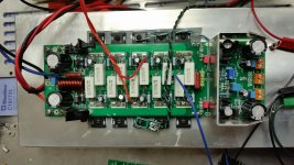
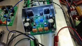
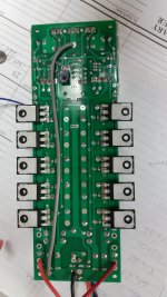
Pre-drivers are MJE340/350. Drivers are NJW0281/0302. Outputs are MJW1302/3281. 107/109 are 33pF Silver Mica. C110/112 are .1uF film and C111/113 are 47uF electros. The ground wire is in place.
Get rid of Csa/Csb .
No Vbe multiplier out on wires , and Ksa/c 1381/3503 as predrivers.
I just checked , I have the faster KSA/C's on 3 of my 4 OPS's.
The sub one has the 340/350's. But it runs as good as the rest.
The NJW0281/0302's are just a little slower (30mhz Ft) than my sanken
drivers (35mhz) - just a little higher Cob.
OS
Silvers are best ! , wish I had them.Are the silver mica caps on the pre-drivers okay or is there a better choice?
You have me doubting myself here .... I'm wondering if a bit more voltage will
bring out any issues.
I've mainly been testing at 40V rails.
EvanC's trafo is waiting ...
OS
Bias setting is even easier now. So far, so good. I'll let it warm up for a couple minutes and beat it up with some sine waves.
Boo. Just stunk up my office. I didn't see any sign of oscillation but I just lost two output devices playing sine waves with no load.
- Home
- Amplifiers
- Solid State
- Slewmaster - CFA vs. VFA "Rumble"