And perhaps parallel one to the resistor of the input filter too; otherwise it wouldn't have much effect if you'd speed up the integrator only. That input filter cap is also going to need a base charge close to its intended target charge.A timed photo-resistor opto would do the trick. Low R at first , then super high
R after 2 seconds. A default fixed R would also be used in the integrator.
OS
Yes,I love using uC's for this kind of stuff. The PSU of my project uses a small one as well for startup control (I follow Vzai's thread on his protection thread as well). But I think that the startup switch in this case could be a very simple RC based one. If you already would have an uC on the amp board or having control wires go to the amp board, then, why not 🙂Almost sounds like a job for Arduino Man... coming soon to your local attraction.
I've updated all the components on my Symasui boards other than Cvs1 and Cvs2. I've left them empty until I can get some stock on them. They still shoot up to 4 volts as soon as the inrush relay turns on. They settle to less than a volt after around 7 seconds. My main power relay comes on 10 seconds after the inrush relay, then the speaker relays come in 3 seconds after that so it's stable long before the speakers engage. This is on cold amps.
Hmmm, I think I'll just leave it as-is then. Mine starts at about 2.5V and is down to 2 or 3mv within about 10 seconds. I don't see the speaker move at all and no sound so I'm not sure what I would gain. I may try piggy-backing that resistor on top of one of the diodes just to see.
Blessings, Terry
Blessings, Terry
Hmmm, I think I'll just leave it as-is then. Mine starts at about 2.5V and is down to 2 or 3mv within about 10 seconds. I don't see the speaker move at all and no sound so I'm not sure what I would gain. I may try piggy-backing that resistor on top of one of the diodes just to see.
Blessings, Terry
Mine may be doing something strange because of the softstart. I'm going to see how the voltage offset compares in relation to the rise time of my supply. Mine seems to be more extreme than anyone else seems to be experiencing so there must be something different about my setup causing it. It's not tripping my protection any more though.
Mine may be doing something strange because of the softstart. I'm going to see how the voltage offset compares in relation to the rise time of my supply. Mine seems to be more extreme than anyone else seems to be experiencing so there must be something different about my setup causing it. It's not tripping my protection any more though.
Jeff, I would try decreasing inrush delay to 2-3 seconds - and increasing the speaker delay - overall settling time may decrease. Main purpose of inrush is to eliminate initial current hump, caused by the big caps charge. But normally after 2-3 seconds they are charged enough, so you can go ahead with shortening the inrush resistor safely, letting the caps charging quicker in the end of the statrup sequence... Just as a suggestion 🙄
Inrush should only last a few cycles (50 or 60 HZ) with a large trafo.
To get the IRON going !😀 The iron (or ferrite) should be under the control
of the windings 😀 in just 20-40 milliseconds. 16.7ms US AC or 20ms euro AC
Caps should settle in (just a few more)milliseconds with a high peak amperage
bridge.
OS
To get the IRON going !😀 The iron (or ferrite) should be under the control
of the windings 😀 in just 20-40 milliseconds. 16.7ms US AC or 20ms euro AC
Caps should settle in (just a few more)milliseconds with a high peak amperage
bridge.
OS
I'm actually going to do the syms first. A servo should beat a DC blocker cap
, as far as settling.
OS
, as far as settling.
OS
The servo in my Symasui, takes a full ten seconds to go from 2.5v to 3mv. It drops to about 300mv within the first 2 seconds and the gradually drops the rest of the way.
Jeff, I would try decreasing inrush delay to 2-3 seconds - and increasing the speaker delay - overall settling time may decrease. Main purpose of inrush is to eliminate initial current hump, caused by the big caps charge. But normally after 2-3 seconds they are charged enough, so you can go ahead with shortening the inrush resistor safely, letting the caps charging quicker in the end of the statrup sequence... Just as a suggestion 🙄
I've been meaning to adjust the delay times, just haven't gotten there yet. Too much on the go here. Lots of new stuff all ready to play with at the same time.
I kind of like a slower inrush. It keeps the lights frum dimming on startup.Inrush should only last a few cycles (50 or 60 HZ) with a large trafo.
To get the IRON going !😀 The iron (or ferrite) should be under the control
of the windings 😀 in just 20-40 milliseconds. 16.7ms US AC or 20ms euro AC
Caps should settle in (just a few more)milliseconds with a high peak amperage
bridge.
OS
I use about 2.5 - 3 seconds for the inrush period. Gives a nice balance between heat (in a big 100R/10W resistor, 230V mains) and sufficient damping of inrush. I've tested this on my supply with empty caps. Really gonna need at least 2 seconds.
Last edited:
I just checked out voltage build time in my supply compared to DC offset in the symasui and they don't really coincide at all. My supply is up to voltage in less than a second so I can definitely shorten that delay with no issue. One thing I have noticed is the offset magnitude changes dramatically with bias current setting. I've been setting mine at 16.5mV across a .22 ohm emitter resistor for 75 mA idle current. Is my math correct?
Is my math correct?
Yep, if you measure across one resistor. I normally measure across two of them - to see an average - then the voltage doubles as well, of course.
Many thanks ....
This forum (and it's members) are top quality.
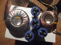
(below) - thanks EvanC ... is the "real man's" trafo. Then - the "hulk"
(bigger one)came in the mail ...
I think my previous Genesis trafo was 800VA , the "hulk" is massive.
I tested all the photographed items ... the "realmans" gives 60+V per rail.
The "hulk" will do 70+ V per rail (with a 500W halogen hooked to it).
That was the only load that could even be measured (as a load ). 😱
OS
This forum (and it's members) are top quality.
(below) - thanks EvanC ... is the "real man's" trafo. Then - the "hulk"
(bigger one)came in the mail ...
I think my previous Genesis trafo was 800VA , the "hulk" is massive.
I tested all the photographed items ... the "realmans" gives 60+V per rail.
The "hulk" will do 70+ V per rail (with a 500W halogen hooked to it).
That was the only load that could even be measured (as a load ). 😱
OS
Attachments
This forum (and it's members) are top quality.
(below) - thanks EvanC ... is the "real man's" trafo. Then - the "hulk"
(bigger one)came in the mail ...
I think my previous Genesis trafo was 800VA , the "hulk" is massive.
I tested all the photographed items ... the "realmans" gives 60+V per rail.
The "hulk" will do 70+ V per rail (with a 500W halogen hooked to it).
That was the only load that could even be measured (as a load ). 😱
OS
You still think three pairs of outputs will do? I'm thinking three pairs on MT200s might be in order.
You still think three pairs of outputs will do? I'm thinking three pairs on MT200s might be in order.
Either them or the Semilab http://products.semelab-tt.com/pdf/ApplicationNoteBipolars.pdf
I also could limit the OPS cap multipliers to make the IPS's clip at <110v p-p.
Doing this , I might never even see any ripple 😱.
OS
Newark stiffed me on 3 pieces but I have 7 and 10 of the devices. Enough to stuff 2 boards at least. The last 3 are coming in January. What inputs are you using? I'll get all the components going.
- Home
- Amplifiers
- Solid State
- Slewmaster - CFA vs. VFA "Rumble"