It thickens slightly with the surge. I will try increasing the sensitivity and see what it looks like.
Low freq instability called 'Motor-boating' (how it sounds) comes to mind.
Often feedback due to Z of PS/GND's and their positions/proxy/layout.
Just a thought if all else fails.
-RNM
Often feedback due to Z of PS/GND's and their positions/proxy/layout.
Just a thought if all else fails.
-RNM
Last edited:
Around 500KHz and rather low amplitude... looks like a local OPS oscillation to me.
Which one are you using?
Which one are you using?
Hi Guys,
I replaced R7&8 with 100R and C6 with 15p. It is better but not gone. This may be a clue. If I hold the DMM test probes across ND- and ground, the pulsing stops. and D10 glows as bright as D9. With the probes removed D10 dims and pulsing starts again.
Thanks, Terry
EDIT; I just noticed that C6 connects to PD+ but there isn't a cap on ND-. Could this have something to do with it?
Last edited:
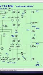
I use a slightly different compensation scheme... difficult to comment, not seeing the exact model. Well, you can slightly increase the base stoppers around VAS:
R26, R34 = 47R
R28, R32 = 22R
That's what I use in my design.
Also, 10-15pF caps between PD+ and base of Q9 as well as ND- and base of Q14 (Miller compensation) should stop the pulsing.
It may be optimized later on, but this is what I would try to reach stability.
R26, R34 = 47R
R28, R32 = 22R
That's what I use in my design.
Also, 10-15pF caps between PD+ and base of Q9 as well as ND- and base of Q14 (Miller compensation) should stop the pulsing.
It may be optimized later on, but this is what I would try to reach stability.
I did go out on a limb with the 2 stage "V" design.
I combined a super high gain dual LTP with a superpair.
I seem to have designed my first oscillator 😱 !
!
My previous CFA and VFA designs were quite tolerant of different VAS
combinations. I used a Hawksford with this one in simulation and also
got an oscillator.
As an experiment , try to run this dual stage IPS with a simple 2 device VAS,
(like below). That would give an impression of it merits.
PS- drop the super-pair entirely. It still has quite low THD without.
OS
I combined a super high gain dual LTP with a superpair.
I seem to have designed my first oscillator 😱
!My previous CFA and VFA designs were quite tolerant of different VAS
combinations. I used a Hawksford with this one in simulation and also
got an oscillator.
As an experiment , try to run this dual stage IPS with a simple 2 device VAS,
(like below). That would give an impression of it merits.
PS- drop the super-pair entirely. It still has quite low THD without.
OS
Attachments
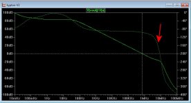
I took a "middlebrook" probe shot of the differences between a plain VAS
(below) and the previous super-pair config - the oscillator 😱 .
The "plain VAS" has no second phase "bump" after the initial drop (arrow)
(after) unity gain . Running "plain" , it is like a "blameless" (wolverine/Badger).
AND should be just as oscillation free.
PS- I'll have to explore this strange interaction between this IPS and
the more "advanced" VAS's.
OS
Attachments
Hi OS,
Do you think this latest version with the super pair removed has any advantage over the Wolverine?
Also, Another thing I am getting is about .4V offset with the servo in place and 1.5V with the servo pulled. This is with no mods. I'm going out to try Valery's suggestions first. If that doesn't work I'll try pulling the super pair. My boards are getting pretty beat up.
Thanks, Terry
My experiments have shown - super-VAS likes Miller (or even TMC, as an enhancement).
It's a high-OLG design, so many factors, including purely implementation matters, play their role. Some Miller capacitance makes the whole thing less dependent on these factors, keeping it more "predictable"... Just as an overall observation 😉
It's a high-OLG design, so many factors, including purely implementation matters, play their role. Some Miller capacitance makes the whole thing less dependent on these factors, keeping it more "predictable"... Just as an overall observation 😉
Also, even more degeneration may be done for IPS - R7, R8 = 220R or even 330R. Still a lot of overall gain.
I'm just trying to think what are the key differences with my tube-based IPS - with around 50R degeneration I've got only 11db gain for the first stage. This one is more "aggressive", so these is still some room to "calm it down"...
I'm just trying to think what are the key differences with my tube-based IPS - with around 50R degeneration I've got only 11db gain for the first stage. This one is more "aggressive", so these is still some room to "calm it down"...
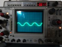
Good news. Being lazy I started with adding 10p across bases of Q9 and Q14 to PD+ and ND-. That did the trick. No oscillation and perfect sine and square waves. Do you think I still need to change out any more of the resistors? The output seems higher than my other IPS. I had to reduce the bias on the OPS compared to the other IPS units I used before. Maybe not a big deal. I will try to get both channels so I can give it a listen.
Also, I discovered the issue with the servo. I was testing at a lower voltage through a light bulb because of the oscillation. Once I took it to full voltage the offset is down to 1 or 2mV.
Thanks, Terry
Also, I discovered the issue with the servo. I was testing at a lower voltage through a light bulb because of the oscillation. Once I took it to full voltage the offset is down to 1 or 2mV.
Thanks, Terry
THx-RNMarsh
We are still at it .. (at least I am).
The CFA IC based design is next on the block.
Something for everyone. 🙂
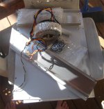
I have to figure who sent me a preamp case ?? Do they want me to
design a pre-amp ? (below - trafo and case).
These IPS's could easily be run at 24V rails and attached to a class A
(headphone/pre-amp) output stage.
A very sunny/warm day here /20C (below 2) .... before the polar air gets here,
must build something....outside.
OS
Attachments
OS, remember the Baxandall pair eliminates Ccb. In your other designs the Ccb of the VAS was loading the output stage. If you're using cascoded predrivers those will also have highly reduced capacitance. In such a case the VAS node probably has less than 1pF of capacitance more from the trace parasitics! The lack of capacitance here can cause oscillation. Maybe this is your problem?
Good news. Being lazy I started with adding 10p across bases of Q9 and Q14 to PD+ and ND-. That did the trick. No oscillation and perfect sine and square waves. Do you think I still need to change out any more of the resistors? The output seems higher than my other IPS. I had to reduce the bias on the OPS compared to the other IPS units I used before. Maybe not a big deal. I will try to get both channels so I can give it a listen.
Also, I discovered the issue with the servo. I was testing at a lower voltage through a light bulb because of the oscillation. Once I took it to full voltage the offset is down to 1 or 2mV.
Thanks, Terry
So adding millers to the super pairs did the trick - Cool. I'll have to see
whether the simulation shows that second "hump" with these.
vzaichenko must of noticed this , as he has these capacitors ??
OS
- Home
- Amplifiers
- Solid State
- Slewmaster - CFA vs. VFA "Rumble"