The older IPS's use ECB inputs (ksa/C 992/1845) , the newer ones BCxxx (CBE).
OS- change R 101/109 on the OPS's to higher value - the IPS is scaled down to what
YOU want. the OPS would never clip.
OS
OS- change R 101/109 on the OPS's to higher value - the IPS is scaled down to what
YOU want. the OPS would never clip.
OS
Last edited:
Either them or the Semilab http://products.semelab-tt.com/pdf/ApplicationNoteBipolars.pdf
I also could limit the OPS cap multipliers to make the IPS's clip at <110v p-p.
Doing this , I might never even see any ripple 😱.
OS
Yeah, and then - as Richard shared his experience the other day - you can give 50-60 Hz to the input from the oscillator and utilize the volume control to use the amp as a high quality lab PSU for testing other designs - connecting rectifier bridge right to the output 😀
!!!!!!!!!!Yeah, and then - as Richard shared his experience the other day - you can give 50-60 Hz to the input from the oscillator and utilize the volume control to use the amp as a high quality lab PSU for testing other designs - connecting rectifier bridge right to the output 😀
Or , running some of these "overkill" amps right into a 500W halogen
(as a load). I've also tested OPS's on an electric range element
or water heater "cal rod" ... most of these are 7 ohm resistance and will pass
1-2KW.
Use the amp to heat up some water for coffee/tea. 😀
OS
(as a load). I've also tested OPS's on an electric range element
or water heater "cal rod" ... most of these are 7 ohm resistance and will pass
1-2KW.
Use the amp to heat up some water for coffee/tea. 😀
OS
I'm putting fans on these. Two 500 watt 4 ohm space heaters.
Same thing as a Walmart ceramic heater.
We need to find new ways to burn all our newly found fracked hydrocarbons
here in N. america ! 😛
OS
It looks like the VFA and CFA are closing in on one another. So, I would expect now that the sonic differences will be getting much smaller.
Though I myself dont use the straight-ahead CFA topolgy - and I am not good at mechanical building things so they look reasonable, I bought a Marantz which uses the CFA topology to listen to. It wasnt a keeper due to limited output stage power but I heard some pretty nice things.
Here is what I derived and use -- when the tube was still the main device, nfb to the cathode was common (but this isnt CFA topology). Such as -

Then when ss came along, the designs copied the tube circuits. Such as -

What some, later did was connect the two of these circuits in parallel using compliments and got the circuit popular in DIYAUDIO (LC's original circuit?). But they were still cap coupled and still needed a large value c in the gain path of the nfb.
What I invented was to reconfigure the two compl circuits into one so they could be dc coupled and eliminated the big electrolytic caps. That is my contribution. Not the CFB Amp topology.
That basic circuit is the one I use now..... a complimentry push-pull from IPS to OPS... With fb to the emitters of the compl input pair. There are many derivatives of it now, of course. And, you are showing some close to it here. Such topology as --

This has been a fun development to watch. I hope to be able to get one (built for me or bought) that meets all my 'specs' to listen to before too long as many of you are doing now. The BV mod CFA version is really appealing to me for its over-all performance.
THx-RNMarsh
Though I myself dont use the straight-ahead CFA topolgy - and I am not good at mechanical building things so they look reasonable, I bought a Marantz which uses the CFA topology to listen to. It wasnt a keeper due to limited output stage power but I heard some pretty nice things.
Here is what I derived and use -- when the tube was still the main device, nfb to the cathode was common (but this isnt CFA topology). Such as -
Then when ss came along, the designs copied the tube circuits. Such as -
What some, later did was connect the two of these circuits in parallel using compliments and got the circuit popular in DIYAUDIO (LC's original circuit?). But they were still cap coupled and still needed a large value c in the gain path of the nfb.
What I invented was to reconfigure the two compl circuits into one so they could be dc coupled and eliminated the big electrolytic caps. That is my contribution. Not the CFB Amp topology.
That basic circuit is the one I use now..... a complimentry push-pull from IPS to OPS... With fb to the emitters of the compl input pair. There are many derivatives of it now, of course. And, you are showing some close to it here. Such topology as --
This has been a fun development to watch. I hope to be able to get one (built for me or bought) that meets all my 'specs' to listen to before too long as many of you are doing now. The BV mod CFA version is really appealing to me for its over-all performance.
THx-RNMarsh
Last edited:
Hi OS,
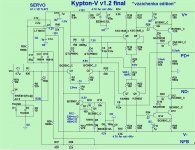
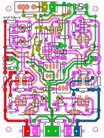
Still struggling with the Krypton-V.
I got the IPS working, sort of, stand alone. with 1k resistors tied to the NFB I can set the current to 10V from PD to ND. If my calculation is correct that should give me 5ma on the VAS. It will play a clean sine wave and even square wave on the scope. However, when I try hooking it up to the OPS it surges in about one second intervals. I also have to turn the bias down a lot. Any suggestions?
Thanks, Terry
________________
Hi Terry, just found the schematic 🙂
5mA through IPS output seems about right.
When you connect OPS and it surghes - can you see something at OPS output with oscilloscope attached?
5mA through IPS output seems about right.
When you connect OPS and it surghes - can you see something at OPS output with oscilloscope attached?
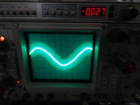
This is what I see on the output with the input shorted
What is the frequency? I can't see the scale...
It's set to 2ms.
I thought maybe it has to do with the servo so I unplugged the servo. The surging changes to about two time per seconds rather than about two seconds per.
I thought maybe it has to do with the servo so I unplugged the servo. The surging changes to about two time per seconds rather than about two seconds per.
OK, that means, this is close to 60Hz. Mains ripple. There's a grounding problem somewhere...
OK, I fixed the grounding problem. I used a cord with an earth ground and connected it to star ground. Still have the surging but that big ripple is gone. When it is surging D10 is dim and it shows the surging. D9 stays bright.
OK, I fixed the grounding problem. I used a cord with an earth ground and connected it to star ground. Still have the surging but that big ripple is gone. When it is surging D10 is dim and it shows the surging. D9 stays bright.
Can you please drop the schematic here - I seem to look at slightly different version...
Also, when you say "surging" - what exactly it does?
The offset goes up and down and so does the bias in about 2 second pulses. The light bulb glows off and on as well.
The offset goes up and down and so does the bias in about 2 second pulses. The light bulb glows off and on as well.
Oscilliscope at the output - does it show straight line or some sort of oscillation? Or the line just jumps up and down together with the offset?
- Home
- Amplifiers
- Solid State
- Slewmaster - CFA vs. VFA "Rumble"