OK, this might not come as an 'approved' modification, but it absolutely does seem to settle the issue with the initial transient, and not a simulation either as I'm listening to it now on real hardware. Hopefully you can see what I have done in this image, if not I'll export another zoomed in a little better.
Tried that , your right ... the servo has the "brute force" approach.
I got 99.3mv - to zero the output.
But , simulate at <100HZ - THD increases considerably.
.01% @ 20hz vs. 2ppm (my last revision).
What would happen if the servo "railed". You are letting the servo
become the "virtual ground" for the NFB.
You want to reduce the settling time of the voltage at the input of the servo ...("Rsl") ,
if the output is at 2.5 V (who cares ?).
This 2.5 V equates to only 3-4mV at the base of Q2 (enough to cancel Q1/2 differences).
PS - the SYM will be my SUB amp ...
my personal selfish reason to
work out this issue. 😀
OS
Last edited:
What I changed is R28 (22KΩ servo isolation resistor) is now omitted with the TL072 output now connected to R25 (820Ω lower feedback resistor) such that R25 is not connected to ground, but rather the servo output. This was just an exploratory change and will need careful evaluation, but it does in fact work to settle things quickly.
Tried that , your right ... the servo has the "brute force" approach.
I got 99.3mv - to zero the output.
But , simulate at <100HZ - THD increases considerably.
.01% @ 20hz vs. 2ppm (my last revision).
What would happen if the servo "railed". You are letting the servo
become the "virtual ground" for the NFB.
You want to reduce the settling time of the voltage at the input of the servo ...("Rsl") ,
if the output is at 2.5 V (who cares ?).
This 2.5 V equates to only 3-4mV at the base of Q2 (enough to cancel Q1/2 differences).
PS - the SYM will be my SUB amp ...
my personal selfish reason to
work out this issue. 😀
OS
There's definitely enough servo headroom to do the job as it is officially implemented. I wasn't even aware of any issue until jwilhelm mentioned it tripping his DC detector and putting the amp into protect. I had been bench testing with no protect circuit in place to trip out.
Myself, I would just alter the start-up detection parameters or simply allow a self-reset on the protection and just enjoy it as-is. Once it is running there is no issue.
I can alter the speaker relay delay easily in the protection circuit. I'm going to try OS's fix. I ran into issues with my protection board tonight, otherwise I would have had it running by now. Are you having any success with the Kypton-V boards Terry?
I can alter the speaker relay delay easily in the protection circuit. I'm going to try OS's fix. I ran into issues with my protection board tonight, otherwise I would have had it running by now. Are you having any success with the Kypton-V boards Terry?
Not yet. I was trying to mark up a schematic when it lost one side. Going to have to go through it again. One problem is that the boards I used are not very good so repairs are damaging the traces. I'll keep tinkering with it but if is a tough nut to crack.
Last edited:
There's definitely enough servo headroom to do the job as it is officially implemented. I wasn't even aware of any issue until jwilhelm mentioned it tripping his DC detector and putting the amp into protect. I had been bench testing with no protect circuit in place to trip out.
Myself, I would just alter the start-up detection parameters or simply allow a self-reset on the protection and just enjoy it as-is. Once it is running there is no issue.
I don't consider this a major issue , but I did "revisit" the design.
#1 - I pushed it to it's limit to "bury" mike B's "symasym".
I especially liked the 2ppm 20hz performance , which is why I used the
servo in the first place. A DC blocker cap gave me .006% 😱.
68p for main compensation and R9/10 @ 68-100R still gives me 33ppm 20k
and a LOT less offset for the servo to "push".
#2 - I did use the Sansui Z for inspiration (servo wise). I overlooked the
"bleeder/shunt" (Rsl) across C12. It is better to deal with the issue
at the uV level than at the VOLT level.
#3 - Consider that to "float" a virtual ground off the servo negates
(Q2) from referencing to the actual input ground.
This could present problems if you hook up a input with a ground loop
or bad ground.
I even tried these changes on the real sansui (22K Rsl) and it shortened
the "pump" of the woofer (sansui has no relays) 😱 .
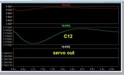
Edit - I went back to the original symasui servo with no "rsl" .. it
takes 4 seconds for C12 to stabilize. (below) You see how sensitive the servo is ,
3uV = 2.75V !!
OS
Attachments
Last edited:
On either of the IPS's (sym or spook) ... just piggyback one of the 2
servo diodes (with "Rsl") ... or tie both diodes together and add a 22-47k in one
of the diode "spots" - no rework.
OS
servo diodes (with "Rsl") ... or tie both diodes together and add a 22-47k in one
of the diode "spots" - no rework.
OS
I don't consider this a major issue , but I did "revisit" the design.
#1 - I pushed it to it's limit to "bury" mike B's "symasym".
I especially liked the 2ppm 20hz performance , which is why I used the
servo in the first place. A DC blocker cap gave me .006% 😱.
68p for main compensation and R9/10 @ 68-100R still gives me 33ppm 20k
and a LOT less offset for the servo to "push".
#2 - I did use the Sansui Z for inspiration (servo wise). I overlooked the
"bleeder/shunt" (Rsl) across C12. It is better to deal with the issue
at the uV level than at the VOLT level.
#3 - Consider that to "float" a virtual ground off the servo negates
(Q2) from referencing to the actual input ground.
This could present problems if you hook up a input with a ground loop
or bad ground.
I even tried these changes on the real sansui (22K Rsl) and it shortened
the "pump" of the woofer (sansui has no relays) 😱 .
OS
Yes, I fully agree that using the servo to create that 'dynamic' virtual ground could have un-intended and undesirable consequences, but I just had to try it. Kids, don't try this one at home; the quick settling likely isn't worth the potential risk. I was unsure what start-up would be like, or how it would actually behave but all the magic smoke stayed in 😀.
I don't have a wide range of capacitor values to play with, so without changing out my pre-filter and integrator caps I just added a 'bleeder' (Rsl) and saw the offset and servo output were both lower in peak value, but it actually took longer to fully stabilize. Looks like the bleeder has two effects, reduce the peak of the transient in trade for settling time (measured this, but forgot to grab the screen output to show it).
Reverting back to the way it was in the first place and again listening the 'issue' is not really an 'issue'. There isn't even any real cone excursion or audible sound.
-140dB is extremely low, even at 20kHz? And which opamp?
Anyhow 10ppb (-160dB) according to post #5001 is impossible.
Cheers, E.
Probably so. Noise floor only.
-RNM
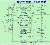
"Spooky" revisited ...
The "issue" is much less pronounced on the "spook".
But , in the name of perfection ... add the "Rsl" across C11 (22-47k).
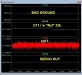
Also ,the "spook" references its NFB from G2. This is not an issue
unless you have a "less than ideal" ground.
(below 1) I simulated a .7V "bad ground" at the input. Perfect with R33
going to G2(L) (arrows - below 2).
NO major rework for the first minor issue , R33 would have to bridge
NFB to any point on the lifted ground.
I will work perfect without these changes , but will be more so with them.
OS
The "issue" is much less pronounced on the "spook".
But , in the name of perfection ... add the "Rsl" across C11 (22-47k).
Also ,the "spook" references its NFB from G2. This is not an issue
unless you have a "less than ideal" ground.
(below 1) I simulated a .7V "bad ground" at the input. Perfect with R33
going to G2(L) (arrows - below 2).
NO major rework for the first minor issue , R33 would have to bridge
NFB to any point on the lifted ground.
I will work perfect without these changes , but will be more so with them.
OS
Attachments
Trace out my board, R33 is referenced to the 'lifted' ground already. I think I made that change because it didn't seem right when I did my layout it out to make the references at different locations, so I'm already there on the grounding point.
The issue is 1/10th the magnitude on Spooky as per prior testing, so definitely no real problem there, though I'm sure the added Rsl will only make things better.
The issue is 1/10th the magnitude on Spooky as per prior testing, so definitely no real problem there, though I'm sure the added Rsl will only make things better.
Last edited:
Some times a simple diode after the high R from the OPS can be used to charge up a small cap to turn on a fet switch. Fet switches in a parallel C or larger value for longer servo time constant. Result is fast initial response and then slower drift servo action.
THx-RNMarsh
THx-RNMarsh
Yes, I fully agree that using the servo to create that 'dynamic' virtual ground could have un-intended and undesirable consequences, but I just had to try it. Kids, don't try this one at home; the quick settling likely isn't worth the potential risk. I was unsure what start-up would be like, or how it would actually behave but all the magic smoke stayed in 😀.
I don't have a wide range of capacitor values to play with, so without changing out my pre-filter and integrator caps I just added a 'bleeder' (Rsl) and saw the offset and servo output were both lower in peak value, but it actually took longer to fully stabilize. Looks like the bleeder has two effects, reduce the peak of the transient in trade for settling time (measured this, but forgot to grab the screen output to show it).
Reverting back to the way it was in the first place and again listening the 'issue' is not really an 'issue'. There isn't even any real cone excursion or audible sound.
If you change caps , lower the Z on the input side of the servo. Sansui
actually used 10u/220K with 47K "rsl". Our Jfet TL072 is higher Z
2.2u/470K for the prefilter is good.
The servo integrator itself is "bled" bi-directionally by both NFB and
R27 to ground , lower impedance here both changes Fc and settling
time.
Then ... there is just having a closer match of Q1/2 - this is not the
perfectly symmetrical "spooky". 😀
OS
Trace out my board, R33 is referenced to the 'lifted' ground already. I think I made that change because it didn't seem right when I did my layout it out to make the references at different locations, so I'm already there on the grounding point.
The issue is 1/10th the magnitude on Spooky as per prior testing, so definitely no real problem there, though I'm sure the added Rsl will only make things better.
Then hook up those bad grounds - Good to go !! A SAFE amp.
Protection Diodes would literally have to smoke before this equated to
a major output offset issue. 🙂
OS
Some times a simple diode after the high R from the OPS can be used to charge up a small cap to turn on a fet switch. Fet switches in a parallel C or larger value for longer servo time constant. Result is fast initial response and then slower drift servo action.
THx-RNMarsh
Example ? (schema) hand drawn is even ok. 🙂
OS
servo C-multiplier
A number of ways -- shunt or series arrangements.... DC voltage may be taken from the speaker output and rectified or taken from DC buss thru RC timing network, as shown. switching in larger C to servo opamp after the RC timing delay. something like this maybe -

You could also place the fet switch across the input C in appropriate way to add more C.
THx-RNMarsh
A number of ways -- shunt or series arrangements.... DC voltage may be taken from the speaker output and rectified or taken from DC buss thru RC timing network, as shown. switching in larger C to servo opamp after the RC timing delay. something like this maybe -
You could also place the fet switch across the input C in appropriate way to add more C.
THx-RNMarsh
Last edited:
Instead of switching another cap into the integrator , why not just
just switch the resistor in the integrator R/C ?
But I get what you are saying - change the Fc of the servo on a timed basis.
I'll add (it) to E. stuarts "super TIS". (or something similar)😀
PS - next "insane" creation. 😛
OS
just switch the resistor in the integrator R/C ?
But I get what you are saying - change the Fc of the servo on a timed basis.
I'll add (it) to E. stuarts "super TIS". (or something similar)😀
PS - next "insane" creation. 😛
OS
Nice thinking, adding a startup switch to reduce the integrator time constant for initial settlement 🙂 I may experiment with this if you're ok with that.A number of ways -- shunt or series arrangements.... DC voltage may be taken from the speaker output and rectified or taken from DC buss thru RC timing network, as shown. switching in larger C to servo opamp after the RC timing delay. something like this maybe -
View attachment 447274
You could also place the fet switch across the input C in appropriate way to add more C.
THx-RNMarsh
Of course.
And increasing R instead is fine also... just not so much that noise or additional offset is created.
Or a fet switch across a second cap (or R) which opens after time delay. A number of ways once you got the idea.
THx-RNMarsh
And increasing R instead is fine also... just not so much that noise or additional offset is created.
Or a fet switch across a second cap (or R) which opens after time delay. A number of ways once you got the idea.
THx-RNMarsh
Last edited:
- Home
- Amplifiers
- Solid State
- Slewmaster - CFA vs. VFA "Rumble"