Okay, that's the measurement floor of the best instruments there are. But what is the lowest measured distortion of the best (op-) amp?
Cheers, E.
Well, my little discrete headphone amp does a measured -126dB. So, that cant be the lowest out there. I think about -140dB from an opamp is the lowest I know of. That opamp is used to produce pure sine waves. The harmonic level of distortion of the sine wave is -140dB.
Does that count?
No, Still4given, it alone cant be heard.
THx-RNMarsh
Last edited:
-140dB is extremely low, even at 20kHz? And which opamp?
Anyhow 10ppb (-160dB) according to post #5001 is impossible.
Cheers, E.
Anyhow 10ppb (-160dB) according to post #5001 is impossible.
Cheers, E.
You could ask that about uhm.. maybe the last 3 pages of posts? Anyways you're right - if/when I post here, it'll be on topic again.What does this have to do with the Slewmaster?
-140dB is extremely low, even at 20kHz? And which opamp?
Anyhow 10ppb (-160dB) according to post #5001 is impossible.
Cheers, E.
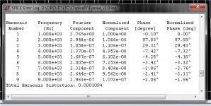
I knew that was impossible, (below 1/2) is the best the LT1057 can do -125db/
1ppm.
Bring it to it's rails , and it don't come close. (it's in 2v p-p buffer mode)
The OPA2134 blows it away ... I can get 3ppm @ 100W with it.
OS
Attachments
What does this have to do with the Slewmaster?
Here is something to do with the slewmaster. !
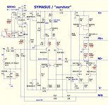
I went back to "square one" ... I used the Sansui Z5900 servo (below 1) for the
Symasui / spooky.
I HAVE the real amp. Hooked up the DMM - .7V drooping to 0 in about 1
second. This amp has done this for 32 years.
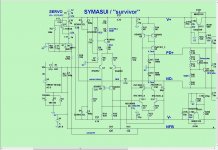
(below 2) ... I simulated the 5900 servo (.3hz Fc) and adjusted the
symasui to the same. Also note R9/10 at LTP - this lowers the native
offset. Note "Rsl" on the prefilter of the servo , this reduces the initial
output surge that fills the cap , which made for a longer discharge (settling).
"Rsl" can be inserted in the D7/8 pads (ride "piggyback").
Note ALL the changes on the whole "symasui" schema ... each has a purpose.
I DO support my designs.
Edit - depending on the gain grouping of Q1/2 - R9/10 can be 68-82R , reducing
initial offset further. Phase margin and loop gain is only slightly altered.
OS
Attachments
Last edited:
Thanks OS. Just so I don't miss anything, that's 4 resistor value changes and one added? I'll try this out tonight.
You mentioned the caps on the servo should be precision NP. What tolerance do you consider precision? Everything I've looked at in the 1% range has a huge lead spacing.
Hi OS,
I updated a schematic. Please check to see if I missed anything.
Thanks, Terry
I missed a few there.
R9/R10 depend on beta grouping. I actually measured my Ksa992/c1845
Cordell semi models - 200X current gain, which equals the "p" gain group.
For the F/Fb group , I subbed some Zetex 800 Hfe PNP's. Here, R9/R10
could be 100R for the same performance. 68R-100R actually reduces the
initial offset that the servo needs to correct.
--- reducing LTP gain reduces "un-servo'ed" native offset. ---
--- High gain groups = 68R-100R low gain groups = 47R-68R ---
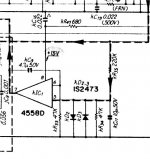
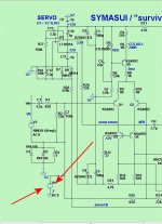
R26/Rsl/C12 is the servo prefilter , I noticed this to be originally "less than
ideal". R26 quickly charged C12 with the inititial "click"/"thump" of the
slewmaster OPS. Even as this was a few 100 mV , until C12 discharged
back through the 1meg (former) R26 .... it created a large voltage at the servo
output. "Rsl" and a smaller R26 allow for a far faster settling time.
--- C12's initial turn-on charge determines settling time ---
R3 and the "lifted ground" issue. By adding "Rsl" , I also solved this problem.
Since R27(servo reference) / "Rsl" and C12 all share a common ground ,
a offset at the lifted ground (R3/D1/2) no longer affects the servo.
Injecting the max .7V into the input ground now equates to <50mv final
OPS offset. "Rsl" references the "servo return" to the same ground
as the IC. (below).
--- a properly working servo CAN last 32 years 😀😀 ---
This also should work with the "spook" , and need no PCB rework.
Edit - one might also consider matching Q1/2 , as well.
OS
Cordell semi models - 200X current gain, which equals the "p" gain group.
For the F/Fb group , I subbed some Zetex 800 Hfe PNP's. Here, R9/R10
could be 100R for the same performance. 68R-100R actually reduces the
initial offset that the servo needs to correct.
--- reducing LTP gain reduces "un-servo'ed" native offset. ---
--- High gain groups = 68R-100R low gain groups = 47R-68R ---
R26/Rsl/C12 is the servo prefilter , I noticed this to be originally "less than
ideal". R26 quickly charged C12 with the inititial "click"/"thump" of the
slewmaster OPS. Even as this was a few 100 mV , until C12 discharged
back through the 1meg (former) R26 .... it created a large voltage at the servo
output. "Rsl" and a smaller R26 allow for a far faster settling time.
--- C12's initial turn-on charge determines settling time ---
R3 and the "lifted ground" issue. By adding "Rsl" , I also solved this problem.
Since R27(servo reference) / "Rsl" and C12 all share a common ground ,
a offset at the lifted ground (R3/D1/2) no longer affects the servo.
Injecting the max .7V into the input ground now equates to <50mv final
OPS offset. "Rsl" references the "servo return" to the same ground
as the IC. (below).
--- a properly working servo CAN last 32 years 😀😀 ---
This also should work with the "spook" , and need no PCB rework.
Edit - one might also consider matching Q1/2 , as well.
OS
Attachments
Last edited:
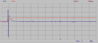
Alternative servo implementation on Symasui...
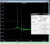
Here's the response utilizing an alternative servo connection. I did not alter servo values from my prior tests, just how the servo is being utilized.
Transient is now ~100mV and settles in about 1s. Also the servo now only needs to output less than 100mV. It even simulated with lower THD, though I don't have suitable equipment to make such a measurement I reality to say if that is true or not.
EDIT: I forgot to mention the blue trace is the start-up transient at the amplifier output before the inductor and the red trace is the output of the servo itself.
Attachments
Last edited:
Give me a few minutes to cook up a quick altered schematic. Actually listening to the modification now... Sounds good so far with only a slight 'tick' at start-up.
Last edited:
No 5pF caps in stock. Is this safe to fire up without any or will it oscillate?
5pf = CLC ?
With C7=68p alone and R9/10 at 68R ... massive stabilty margin.
Clc just boosts phase margin if you push this amp to it's limit
(1.5mhz UG and max CLG).
Absolutely won't oscillate !!

OS
OK, this might not come as an 'approved' modification, but it absolutely does seem to settle the issue with the initial transient, and not a simulation either as I'm listening to it now on real hardware. Hopefully you can see what I have done in this image, if not I'll export another zoomed in a little better.
Attachments
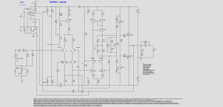
Without making me dig through it again, can you explain which values you changed?
Thanks, Terry
Thanks, Terry
- Home
- Amplifiers
- Solid State
- Slewmaster - CFA vs. VFA "Rumble"