Q12 bridge??No, It is fixed ... (same as before)updated labels + Q12 bridge.
OS
Attachments


Last edited:
Here
Attachments
Last edited:
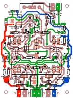
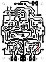
Q12 bridge??
(below) ...
Just use the jumper to bridge to the base of Q12.
Sorry - it was hidden under the silk.
OS
Attachments
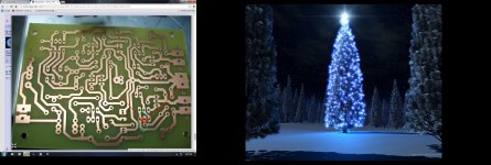
Oh tanks Terry.Here
I need an ophthalmologist soon!
PS thanks OS!Maybe tomorrow it is alive.
Terry what about yours?
PS what a beautiful tree!!!!!
Last edited:
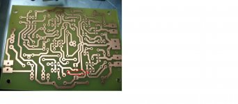
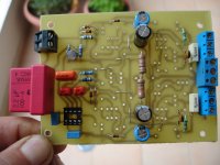
I found it because with iron transfer I always have to go over each trace to check for bridges and gaps. When I got to that transistor I saw that the base pad didn't attach to anything. That is when I noticed the BMP was wrong. Hence the warning.
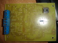
Mine is complete but I have a doctor's appointment so will test in about an hour. I didn't have any 27p caps so I used 33p hopefully that will work.
Blessings,Terry
Mine is complete but I have a doctor's appointment so will test in about an hour. I didn't have any 27p caps so I used 33p hopefully that will work.
Blessings,Terry
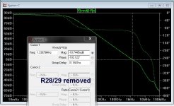
Don' go lower than 22p or higher than 47p.
-below 22p , you run out of phase margin.
-above 47p - all is safe .... BUT , slew rate begins to drop.
27-33p is quite ideal (below).
Also - omit R28/29 for 20+ db more gain , this will also drop 8ppm to 1-2ppm
(as opposed to changing the feedback resistors).
OS
-below 22p , you run out of phase margin.
-above 47p - all is safe .... BUT , slew rate begins to drop.
27-33p is quite ideal (below).
Also - omit R28/29 for 20+ db more gain , this will also drop 8ppm to 1-2ppm
(as opposed to changing the feedback resistors).
OS
Attachments
I found it because with iron transfer I always have to go over each trace to check for bridges and gaps. When I got to that transistor I saw that the base pad didn't attach to anything. That is when I noticed the BMP was wrong. Hence the warning.
Mine is complete but I have a doctor's appointment so will test in about an hour. I didn't have any 27p caps so I used 33p hopefully that will work.
Blessings,Terry
I'm really looking forward to your listening impression Terry.

In the response curve ?
If you want my opinion, never allow this. Never !
Christophe, this is what I mean
Attachments

Don't you think there is some resonance ?Christophe, this is what I mean
Can-you provide the response curve ?
I fired it up but the bias adjustment is not working. I'm going to have to do some research. I will get to that tomorrow.
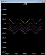
Slewmaster bias explained.
Terry , (below) is the expected range of "VAS I adj." on the kypton-c.
All the slew IPS's have basic current adjustment.
Symasui , wolverine, and spooky are CCS based. CCS's adjust from 1-2+ ma ,
which equates to 4-7ma at the VAS collector(s).
CFA-X also has CCS's (same setup).
"Kypton-C" has a fixed op-amp /mirror based current scheme. It's
adjustment is right AT the VAS. Final current is controlled by changing
the gain of the Baxandall (super-pair) directly. Slightly less range unless
you manipulate R24/25 values (larger value trimmer).
Edit - now I see the issue !! This amp is different - you are adjusting the RATIO of the super- pair/ led current
versus the VAS cascode current. The VAS main emitter resistors would show very little change ,
but LED If and Cascode Ic would proportionately have a wide response.
This is the same as simply adjusting the LED current on any of the Hawksford based IPS's.
LED's should get brighter ??
OS
Attachments
Last edited:
This way?Don' go lower than 22p or higher than 47p.
-below 22p , you run out of phase margin.
-above 47p - all is safe .... BUT , slew rate begins to drop.
27-33p is quite ideal (below).
Also - omit R28/29 for 20+ db more gain , this will also drop 8ppm to 1-2ppm
(as opposed to changing the feedback resistors).
OS
Attachments
This way?
Yes , 20k goes down a few PPM <10k drops to 1ppm !
Terry , voltage readings please. 😀
OS
Don't you think there is some resonance ?
Can-you provide the response curve ?
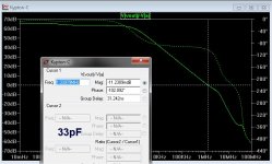
What exactly response do you mean? Frequency/phase, open loop / closed loop, etc.?
Frequency/phase, closed loop.What exactly response do you mean?
I worry about the ~200KHz strange thing...
R14-R17?
R14,17 IS 39R OR 68-82R?
R14,17 IS 39R OR 68-82R?
Attachments

Last edited:
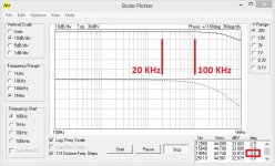
Frequency/phase, closed loop.
I worry about the ~200KHz strange thing...
Closed loop response is very good, no problem at all (this is a real life prototype measurement). See more details >HERE<
~200KHz strange thing is only visible when I try to analyze the circuit open loop in simulator, injecting the signal into the feedback loop and measuring the gain and phase (somewhat similar to TIAN probe, but using Bob Cordell method)...
I don't even think it deserves so much of our attention - maybe just as a "theoretical" excercise...
Attachments
- Home
- Amplifiers
- Solid State
- Slewmaster - CFA vs. VFA "Rumble"