I like the open loop bandwith on the thing. I think that Valery has explored that way of folding over, One thing you can say about that is good symmetry in the IPS
But it has that crazy phase response. I've yet to try lag comp. on both
stages.
I actually degenerated the hell out of it ... just to get it running.
It likes to oscillate 🙁.
Once I figure out the right compensation , it outperforms ALL others.
OS
stages.
I actually degenerated the hell out of it ... just to get it running.
It likes to oscillate 🙁.
Once I figure out the right compensation , it outperforms ALL others.
OS
Now what if you strip R21 and R24 (1K) and replace them with wilson current mirrors to fold over to the VAS output rail? This way you don't have 3 gain stages and you can lower the degen again of the 2nd/1st stage.
But it has that crazy phase response. I've yet to try lag comp. on both
stages.
I actually degenerated the hell out of it ... just to get it running.
It likes to oscillate 🙁.
Once I figure out the right compensation , it outperforms ALL others.
OS
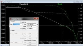
Hi OS, look at what I ended up with in terms of compensation - >HERE<
TMC plus lead cap plus RC filter at LTP.
It also shows certain sagging at around 200KHz and then this hump at around 3MHz, but is doesn't hurt and I don't see that sagging influence at the live prototype (although, it seems to be a bit less "evil" than yours).
I would also try the base stoppers between the double LTPs and VAS transistors...
My prototype is rock stable.
Cheers,
Valery
Yes , I see your lead/lag. You need very little (150p/6.8p)
You do understand that the tubes (or the pioneer FET first ltp) have much
lower gain than the BJT's.
(below 1) .. I compromised with a 2 stage LTP driving a level shifted
baxandall/ hawksford VAS.
For the BJT first stage I used 150R/.001u,which got me down to <2mhz unity gain.
I had too much gain margin at 20-30K ... so I took lead comp. right off
the VAS output -C11 (. I finally "tamed" the gain 😀 . (below 2).
Even "tamed", I still have 15db margin at 20k - 4ppm (below 3).
Using c11 lead , I saw no effect using local miller around the baxandall's.
Your tube IPS is cool !😎 The tubes essentially take the place of the FET's
in my previously posted sansui hybrid front end.
PS- another aspect of this IPS is it's 200V+ slew. It's CFA fast !
OS
Attachments

Last edited:
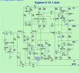
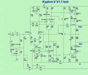
I like this one !
Schema+asc below.
Should not build the same stuff again and again. Different is good
.
OS
Like GLA?
Finally, you make GLA IPS 😎
A very cool way of folding from the 2-nd LTP to push-pull VAS, "mirroring down" the left shoulder 
5pF Miller is also cool 🙂
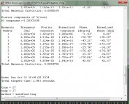
I have just checked the gain distribution between the stages in the current version of my hybrid (together with LatFET OPS).
It goes like this (1KHz):
1-st LTP (tube) OLG: 11db
2-nd LTP OLG: 24.5 db
VAS OLG: 58.1db
Overall OLG: 93.6db
CLG: 28.9db
LG: 64.7db
OLG THD: 0.5%
This kind of "gradually increasing" OLG distribution, in combination with rather good open loop linearity (less than 0.5% THD at high swing), ensures excellent handling of fast transients, creating very good conditions for NFB to work with.
The other point - at 20KHz it is still a pretty good open loop performer (lag compensation is in place):
1-st LTP (tube) OLG: 10.5db
2-nd LTP OLG: 17.5 db
VAS OLG: 49.7db (slightly killed by compensation)
Overall OLG: 77.7db
CLG: 28.9db
LG: 48.8db
OLG THD: 0.6%
Note - almost no difference for the 1-st LTP (tube is cool 😉).
A rather decent "microphone amplifier", capable of driving 8 ohm directly 😀
As soon as you close the loop, the bandwidth goes up to more than 500KHz (still maintaining stability), so 20KHz becomes the lowest 10% of it 😎 Handled "easily"...
In combination with rather high slew rate, as you say - "CFA-fast VFA".
Blurring the boundaries 😉
Key listening impression is very similar to the good CFA - very natural sound, reproducing all the smallest nuances.
I think, we're "on the right track" 😎
Cheers,
Valery
5pF Miller is also cool 🙂
I have just checked the gain distribution between the stages in the current version of my hybrid (together with LatFET OPS).
It goes like this (1KHz):
1-st LTP (tube) OLG: 11db
2-nd LTP OLG: 24.5 db
VAS OLG: 58.1db
Overall OLG: 93.6db
CLG: 28.9db
LG: 64.7db
OLG THD: 0.5%
This kind of "gradually increasing" OLG distribution, in combination with rather good open loop linearity (less than 0.5% THD at high swing), ensures excellent handling of fast transients, creating very good conditions for NFB to work with.
The other point - at 20KHz it is still a pretty good open loop performer (lag compensation is in place):
1-st LTP (tube) OLG: 10.5db
2-nd LTP OLG: 17.5 db
VAS OLG: 49.7db (slightly killed by compensation)
Overall OLG: 77.7db
CLG: 28.9db
LG: 48.8db
OLG THD: 0.6%
Note - almost no difference for the 1-st LTP (tube is cool 😉).
A rather decent "microphone amplifier", capable of driving 8 ohm directly 😀
As soon as you close the loop, the bandwidth goes up to more than 500KHz (still maintaining stability), so 20KHz becomes the lowest 10% of it 😎 Handled "easily"...
In combination with rather high slew rate, as you say - "CFA-fast VFA".
Blurring the boundaries 😉
Key listening impression is very similar to the good CFA - very natural sound, reproducing all the smallest nuances.
I think, we're "on the right track" 😎
Cheers,
Valery
Yes , we are on the "right track' .... and yes .. Bimo - the GLA 😎 .
This GLA is way more stable.
GLA had no current sources 🙁 , a "bombed out" 3 transistor level shifter
VAS. GLA (original) actually used FET's as 1st stage.
Vzaichenko's description of the OLG sounds right. My BJT is 25db/25db/40db
(1st/2nd/VAS) - 90db total. I had to reduce VAS gain (150R Re's).
I also tried your symmetric TMC compensation. No real improvements to
this BJT version.
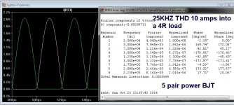
Below 1/2/3 ... best I can do 🙄
4 ppm 25hz 200w , drops to sub ppm 1K-10K ... back to 5ppm at 25K (4R).
I used 2.2 -2.7p for that "cool" miller and lead.
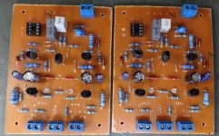
Time for a board ...😀
OS
This GLA is way more stable.
GLA had no current sources 🙁 , a "bombed out" 3 transistor level shifter
VAS. GLA (original) actually used FET's as 1st stage.
Vzaichenko's description of the OLG sounds right. My BJT is 25db/25db/40db
(1st/2nd/VAS) - 90db total. I had to reduce VAS gain (150R Re's).
I also tried your symmetric TMC compensation. No real improvements to
this BJT version.
Below 1/2/3 ... best I can do 🙄
4 ppm 25hz 200w , drops to sub ppm 1K-10K ... back to 5ppm at 25K (4R).
I used 2.2 -2.7p for that "cool" miller and lead.
Time for a board ...😀
OS
Attachments

Yes , we are on the "right track' .... and yes .. Bimo - the GLA 😎 .
This GLA is way more stable.
GLA had no current sources 🙁 , a "bombed out" 3 transistor level shifter
VAS. GLA (original) actually used FET's as 1st stage.
Vzaichenko's description of the OLG sounds right. My BJT is 25db/25db/40db
(1st/2nd/VAS) - 90db total. I had to reduce VAS gain (150R Re's).
I also tried your symmetric TMC compensation. No real improvements to
this BJT version.
Below 1/2/3 ... best I can do 🙄
4 ppm 25hz 200w , drops to sub ppm 1K-10K ... back to 5ppm at 25K (4R).
I used 2.2 -2.7p for that "cool" miller and lead.
Time for a board ...😀
OS
I've tried most of these compensation schemes and came to a pretty simple
conclusion - you basically trade phase margin for OLG.
TMC when optimized seems to trade phase margin early, say around 10kHz,
and then you get it back later.
Even for a fairly simple circuit, with TMC you can get the simulated
distortion down to ridiculously low levels (0.000006% / 1 ohm / 30V pk /
1kHz) but there's always a phase margin trade off somewhere.
I think there needs to be some serious listening tests to see what matters
subjectively -
a) very healthy phase margin with some distortion trade off
b) super low distortion with a phase margin trade off.
My gut feeling is that a) will sound better but I will find out soon.
One other thing that not many have considered here is good distortion, even
at fairly high frequencies when driven from a higher impedance.
A lot of people will want to drive these amps from some form of passive
vol control. As such there can be a significant performance trade off.
I always do a test simulation with say 10k source R to see if there is
sensitivity to this. Low sensitivity to high source R means a much better
chance of good sound in a variety of 'real world' situations.
We do tend to get a bit carried away with sims and forget the real world.
🙂 🙂
cheers
T
Very valid point on source impedance sensitivity.
I also agree that it's likely better having a rock stable amplifier with slightly higher distortion than the one with very low distortion but poor phase margin.
Cheers,
Valery
I've tried most of these compensation schemes and came to a pretty simple
conclusion - you basically trade phase margin for OLG.
That what they did with the original sansui "GLA" (Z5900).
Only 7 transistors in the input stage /VAS. They "cranked" it up to 120db
OLG ... and it had dubious phase margin like this.
They then added a huge 47pF lead cap back from the output to increase
that margin at unity gain.
This allowed that 7 device amp (2 ltp + 2ltp + 3 VAS) to have .002-005%.
All the "economical" old Japanese VFA amps in the 80's used this trick.
With more parts (CCS's + cascoded VAS's), you can get that same performance with far less gain (90db).
Still , I had to sacrifice sub PPM THD for margin. .5ppm to 5ppm was the price ,
but I like having almost 90 degree margin at unity gain - no one
will yell at me for causing more "magic smoke" in the world. 😀
OS
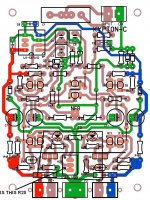
I'm confused a little.Are this Kypton-C the final version for testing 😕Posted below - the toner "works" ( I found the "bugs").
Toner image is the big .BMP image 300dpi/ 76 X 102mm.
OS
Last edited:
I'm confused a little.Are this Kypton-C the final version for testing 😕
I hope so
Attachments
😱Hi Terry you manage to finish when i'm confused😡I hope so
I wish you the best (no smoke)😀
Waiting for your results.

Best Regards.
Last edited:
Green/blue/ white/uv (2.6v or above) 3.2v or above is best -blue/uv .... wow !! Terry - beat Thimios - we were all taking
bets around here 😀 .
OS
bets around here 😀 .
OS
Last edited:
That what they did with the original sansui "GLA" (Z5900).
Only 7 transistors in the input stage /VAS. They "cranked" it up to 120db
OLG ... and it had dubious phase margin like this.
They then added a huge 47pF lead cap back from the output to increase
that margin at unity gain.
This allowed that 7 device amp (2 ltp + 2ltp + 3 VAS) to have .002-005%.
All the "economical" old Japanese VFA amps in the 80's used this trick.
With more parts (CCS's + cascoded VAS's), you can get that same performance with far less gain (90db).
Still , I had to sacrifice sub PPM THD for margin. .5ppm to 5ppm was the price ,
but I like having almost 90 degree margin at unity gain - no one
will yell at me for causing more "magic smoke" in the world. 😀
OS
90 deg phase margin at UG is extremely conservative, generally the 'safe'
phase margin is required at 30dB OLG, or whatever the closed loop gain of
the amp is.
Having said that, I am sure you will have great stability with around 90 deg
at unity OLG - and it may pay sonic benefits. Was it Pass that said the
further away from instability an amp is, usually subjectively the better?
I'm going to have a really good play with all these compensation schemes
and see how they affect the sonics.
T
OS please look at thisGreen/blue/ white/uv (2.6v or above) 3.2v or above is best -blue/uv .... wow !! Terry - beat Thimios - we were all taking
bets around here 😀 .
OS
Attachments
- Home
- Amplifiers
- Solid State
- Slewmaster - CFA vs. VFA "Rumble"