Makes sense 😎
I try 🙄 .
I have often wondered what makes for a "cult" amp. (diehard fans).
JVC describes the clamp/error correction as the ability to:
A: "(1) distor-
tion caused by speaker motion (by rendering counterelectromotive
force harmless). hah ! i.e. correcting what NFB can not.
B:low TIM as a by-product.
The rest of the description is "smoke".
This sort of explains the "CFA" thing. Does the back EMF of a real world
speaker load feed back into "current on demand" in a CFA based
amp.?
The super short (current) FB loop of the CFA-X "sees" the loudspeaker ??
So , the slew might not be the winning attribute , after all.
I MUST find out. 😱
OS
A cap across them ?THOSE DIRTY DIODES.
Just compare with an oscilloscope the signal at the base of the VAS ?Does the back EMF of a real world
speaker load feed back into "current on demand" in a CFA based
amp.?
One amp on resistive load, an other with real speakers, both with the same musical signal.
Last edited:
Get yer toner ready .. Thimios
Next -gen CFA-X
I'm really "on" the kypton-C .. I'll finish tonight/tomorrow - very soon.
Both the C/V use the same VAS , so both should be
wrapped up this weekend.
I did update the CFA "kypton". Lazy cat's remark on the summed capacitors
(R10/11) might have virtue.
Populate R8 only(jumper R8a/b) - get summed current feedback , Jumper R8
and populate R8a/b with 68-82R to get the "classic" cfa-x feedback.
Simulation shows NO THD or Bode deviations either way ... but - options are nice.
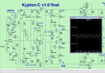
(below 1/2) is updated kypton-c schema and layout "style". (almost jumperless).
Also , "deciphered" why this design has 90db psrr .... switched op-amp for
either a standard CCS and just ground .....found inferior performance.
The OP-AMP's internal CCS's are the key , in fact ...
a better op-amp than the TL072 will drive the PSRR up to @100db.
So , I have a servo plus a precision current source by just using the chip !
Tested servo failure - NO servo = just the native offset (input pair Hfe).
A shorted servo would only make for +/- 1 V main offset.
You "audio purists" need not worry about an IC fouling up the VSSA "sound",
using the IC or just grounded is the same 8ppm THD20K/harmonic structure.
You can also reduce degeneration on R11-14 to 220R - you get 6db more CLG
(4ppm 100w 20k). NOT bad for a "toy" amp.
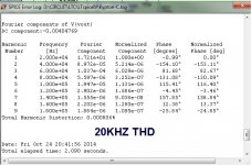
PS- PSRR and 10HZ-20k THD (below 3/4/5) .... lows are NO issue with this one !
Get ready, terry/thimios ! 😱
Edit - slew is 400v/us , clip is perfect - best (simple) CFA by far.
OS
Next -gen CFA-X
I'm really "on" the kypton-C .. I'll finish tonight/tomorrow - very soon.
Both the C/V use the same VAS , so both should be
wrapped up this weekend.
I did update the CFA "kypton". Lazy cat's remark on the summed capacitors
(R10/11) might have virtue.
Populate R8 only(jumper R8a/b) - get summed current feedback , Jumper R8
and populate R8a/b with 68-82R to get the "classic" cfa-x feedback.
Simulation shows NO THD or Bode deviations either way ... but - options are nice.
(below 1/2) is updated kypton-c schema and layout "style". (almost jumperless).
Also , "deciphered" why this design has 90db psrr .... switched op-amp for
either a standard CCS and just ground .....found inferior performance.
The OP-AMP's internal CCS's are the key , in fact ...
a better op-amp than the TL072 will drive the PSRR up to @100db.
So , I have a servo plus a precision current source by just using the chip !
Tested servo failure - NO servo = just the native offset (input pair Hfe).
A shorted servo would only make for +/- 1 V main offset.
You "audio purists" need not worry about an IC fouling up the VSSA "sound",
using the IC or just grounded is the same 8ppm THD20K/harmonic structure.
You can also reduce degeneration on R11-14 to 220R - you get 6db more CLG
(4ppm 100w 20k). NOT bad for a "toy" amp.
PS- PSRR and 10HZ-20k THD (below 3/4/5) .... lows are NO issue with this one !
Get ready, terry/thimios ! 😱
Edit - slew is 400v/us , clip is perfect - best (simple) CFA by far.
OS
Attachments


I'm here🙂Next -gen CFA-X
I'm really "on" the kypton-C .. I'll finish tonight/tomorrow - very soon.
Both the C/V use the same VAS , so both should be
wrapped up this weekend.
I did update the CFA "kypton". Lazy cat's remark on the summed capacitors
(R10/11) might have virtue.
Populate R8 only(jumper R8a/b) - get summed current feedback , Jumper R8
and populate R8a/b with 68-82R to get the "classic" cfa-x feedback.
Simulation shows NO THD or Bode deviations either way ... but - options are nice.
(below 1/2) is updated kypton-c schema and layout "style". (almost jumperless).
Also , "deciphered" why this design has 90db psrr .... switched op-amp for
either a standard CCS and just ground .....found inferior performance.
The OP-AMP's internal CCS's are the key , in fact ...
a better op-amp than the TL072 will drive the PSRR up to @100db.
So , I have a servo plus a precision current source by just using the chip !
Tested servo failure - NO servo = just the native offset (input pair Hfe).
A shorted servo would only make for +/- 1 V main offset.
You "audio purists" need not worry about an IC fouling up the VSSA "sound",
using the IC or just grounded is the same 8ppm THD20K/harmonic structure.
You can also reduce degeneration on R11-14 to 220R - you get 6db more CLG
(4ppm 100w 20k). NOT bad for a "toy" amp.
PS- PSRR and 10HZ-20k THD (below 3/4/5) .... lows are NO issue with this one !
Get ready, terry/thimios ! 😱
Edit - slew is 400v/us , clip is perfect - best (simple) CFA by far.
OS
PS a great earthquake keeps us awake tonight

Last edited:
Oh shoot, I had the iron plugged in. 😀
I don't lie ! I'm at the servo now (listening to heavy metal) 😀
In N. america - tomorrow morning !
This really is QUITE the advancement over the current CFA. It does better
than some precision CFA op-amps at 10X the power.
Since the servo/mirrors ARE the source of the "refinements", I will over-design it.
PS- (below) MAN! ,that is a lot of CFA gain - most don't(won't) do this.
.... 1ppm THD with this much CLG.
OS
Attachments

Last edited:
The remark, I think it was me 🙂Lazy cat's remark on the summed capacitors
(R10/11) might have virtue. .... best (simple) CFA by far.
BTW, just have a quick look at those, if not yet done, about the interest to remove them :
www.esperado.fr - VSSA with Diamond input and DC servo
http://www.esperado.fr/vssa-diamond/dvssa.php
Look and help debug these.
I was "rusty" .... hard work !!

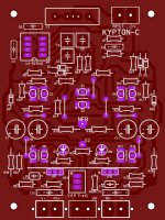
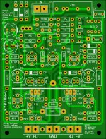
Looked at the "pro ones" (JK's boards) altered my style a little.
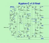
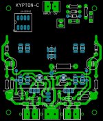
#1 -how it would look .😀
#2 - the schematic I went with - (used the split current feedback scheme)
If anyone wonders why I have the 3 caps in the servo (C3-C4-C9) , it
gives me picovolt ripple at the mirror reference and 102db PSRR.
The servo WILL NOT "corrupt" this amp's sound.
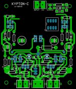
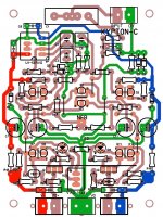
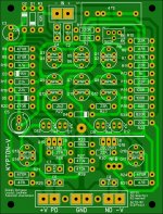
#3 - grounding and power traces. (a "maze" of green).
I could output the toners X-fers now , but .... look them over first.
(Terry/Thimios).
OS
I was "rusty" .... hard work !!
Looked at the "pro ones" (JK's boards) altered my style a little.
#1 -how it would look .😀
#2 - the schematic I went with - (used the split current feedback scheme)
If anyone wonders why I have the 3 caps in the servo (C3-C4-C9) , it
gives me picovolt ripple at the mirror reference and 102db PSRR.
The servo WILL NOT "corrupt" this amp's sound.
#3 - grounding and power traces. (a "maze" of green).
I could output the toners X-fers now , but .... look them over first.
(Terry/Thimios).
OS
Attachments
Last edited:
Kypton - N ???
The "NAD" , set up like the kypton-c , performs just as flawlessly.
Servo had to be inverted (uninverted 🙂 )
nV offset - 100db PSRR - awesome !!
BUT , it could not match the "vssa" core transconductance stage.
(below)... could only get 20ppm 100V THD20k, where my "C" can get
@5ppm.
VSSA is the better "engine" , even with the same enhancements. 😕
PS - it would still be a very , very good amp (.002% vs .0005% - whats the
difference ?? )
OS
Attachments

Tomorrow will be a full day😱Look and help debug these.
I was "rusty" .... hard work !!
Looked at the "pro ones" (JK's boards) altered my style a little.
#1 -how it would look .😀
#2 - the schematic I went with - (used the split current feedback scheme)
If anyone wonders why I have the 3 caps in the servo (C3-C4-C9) , it
gives me picovolt ripple at the mirror reference and 102db PSRR.
The servo WILL NOT "corrupt" this amp's sound.
#3 - grounding and power traces. (a "maze" of green).
I could output the toners X-fers now , but .... look them over first.
(Terry/Thimios).
OS
Try working with lower resistor-values in your diamond. R14-R17-R30 R61, also your FB network has too high values.
The remark, I think it was me 🙂
BTW, just have a quick look at those, if not yet done, about the interest to remove them :
www.esperado.fr - VSSA with Diamond input and DC servo
http://www.esperado.fr/vssa-diamond/dvssa.php
When I first saw the LC design, I asked the designer to bring it up to date by reconfiguring it so those large caps were not needed. He didnt do it but Esperado did and then added servo to it. Now if you look at the LC circuit without diamond input, it is the same as I introduced back in the late '70's.as a new line stage topology (published in TAA).
The discussions/forum on what is a CFA has shown benefits of the diamond input stage. I called it an 'expansive' character in that forum. Wheres, differential IPS is 'compressive' characteristic (as I showed in that forum). Esperado has done the smart thing and combined it with one of the best topologies to make a high performance but kept the simple design.
In another forum I challenged others to make the simplest line level stage they could and equal or exceed certain minimum specs. In this VSSA-Diamond we get what I have been suggesting and with the expected excellent results with minimal circuitry. When I get back to the states, I am going to try to make it and listen and hopefully get the power level up to where i need it... at least 200W/8. And, maybe tweek it a little. I would like to see more OPS isolation for real world speaker loading affects.
Now, many others here have also produced truly great Current-Feedback amplifier designs with great sophistication... but in too many cases the complexity has far exceeded my ability (or my patience) to build them.
There is no way I am going to etch my own pcb..... that is a deal killer for me. But if the CFA-X had pcb available I might get the parts together to try it. I especially like the psrr. At least it isnt laid out for smd !!
THx-RNMarsh
Last edited:
When I first saw the LC design, I asked the designer to bring it up to date by reconfiguring it so those large caps were not needed. he didnt do it but esperado did. Now if you look at the LC circuit without diamond input, it is the same as I introduced back in the late '70's.as a line stage (published in TAA).
The discussions/forum on what is a CFA has shown benefits of the diamond input stage. I called it an 'expansive' character in that forum. Esperado has done the smart thing and combined it with one of the best topologies to make a high performance but simple design. When I get back to the states, I am going to try to make it and listen and hopefully get the power level up to where i need it... at least 200W/8. And, maybe tweek it a little.
THx-RNMarsh
I used an input stage in all my CFA input buffer as I used it in the GainWire mk2 line amp. It is not exactly diamond nor Baxandall super pair, something between, I don't know how to call it but no degradation of the sound as LC said about diamond, just very clean and expansive sound.
Damir
I used an input stage in all my CFA input buffer as I used it in the GainWire mk2 line amp. It is not exactly diamond nor Baxandall super pair, something between, I don't know how to call it but no degradation of the sound as LC said about diamond, just very clean and expansive sound.
Damir
I love your design as well. It is a very, very nice topology and one I would also consider buying. But taking the time to build it? Can you please get someone to make a kit of it?
Ditto Andrew - I love his work with CFA also. But I just cant do the time thing involved. Get someone to make a kit of it and I'll buy them. I really want good work to be heard more. Get it up and out of here and into mainstream. Go make some money on your work..... or commission others to make it and take a royalty. I support that... being as I would rather design or buy but not mfr or build.
Ostripper.... great effort as well.... but nothing for me to buy.... build from scratch only. Etch my own pcb? Sigh.
Keep up the great work !! But turn it into something we can buy, too. DIY Store? eBay?
THx-RNMarsh
Last edited:
Jason definitely has a style of his own when laying out circuit boards.Look and help debug these.
I was "rusty" .... hard work !!
Looked at the "pro ones" (JK's boards) altered my style a little.
#1 -how it would look .😀
#2 - the schematic I went with - (used the split current feedback scheme)
If anyone wonders why I have the 3 caps in the servo (C3-C4-C9) , it
gives me picovolt ripple at the mirror reference and 102db PSRR.
The servo WILL NOT "corrupt" this amp's sound.
#3 - grounding and power traces. (a "maze" of green).
I could output the toners X-fers now , but .... look them over first.
(Terry/Thimios).
OS
It is MOSFETs... (quasi infinite current gain where speakers can generate a signal ;-)I would like to see more OPS isolation for real world speaker loading affects.
Oh, one of the advantages of this modified diamond input stage is it use only one line to return feeback. While, in the L.C. nice amp, each difference in value between the two feedback resistances will increase distortion.
Last edited:
Look and help debug these.
I was "rusty" .... hard work !!
Looked at the "pro ones" (JK's boards) altered my style a little.
#1 -how it would look .😀
#2 - the schematic I went with - (used the split current feedback scheme)
If anyone wonders why I have the 3 caps in the servo (C3-C4-C9) , it
gives me picovolt ripple at the mirror reference and 102db PSRR.
The servo WILL NOT "corrupt" this amp's sound.
#3 - grounding and power traces. (a "maze" of green).
I could output the toners X-fers now , but .... look them over first.
(Terry/Thimios).
OS
I noticed a couple bugs in the silkscreen. R12 & R13 are reversed (No effect on operation anyway). The pot should be R24. R24 should be R25. R28 should be R29. R27 on the left should be R28. There are two R27s. Proofing yours showed me a few errors on mine.
Last edited:
- Home
- Amplifiers
- Solid State
- Slewmaster - CFA vs. VFA "Rumble"