Yes I checked it with a 3v supply and a resistor. The weird thing is it lights about two seconds after I switch off the power and stays on until the PSU has drained down.
That something conducting as the voltage drops. It conducts as a cap drains backwards.
Something's causing DC on your input. Is Q1 running hot as well? Or does it possibly have a solder bridge from emitter to base?
I think it's something on the positive side at the input end. It has almost a volt positive on the input. Q2 will be conducting quite a bit.
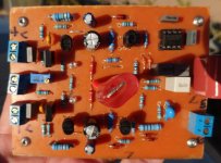
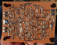
Is there a bridged connection on the transistor at the top of the right picture in the middle of the board? I need to find a picture of the silk to give you a transistor number.
Try replacing Q10
I could but it measures fine, vbe is .610V and it measures good with a diode test.
Jeff,
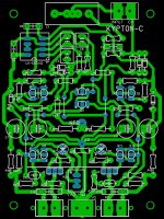
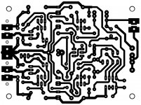
I'm attaching a mirror of the foil and the component view.
Attachments
Last edited:
Ideal 35V readings ....
Remember the zeners ! R18/19 with a 35V supply needs to be reduced
to 2.2K.
(below) are the ideal 35V simulated readings.
Edit- emitters of Q7 and Q12 are exactly +/- 34V
OS
Remember the zeners ! R18/19 with a 35V supply needs to be reduced
to 2.2K.
(below) are the ideal 35V simulated readings.
Edit- emitters of Q7 and Q12 are exactly +/- 34V
OS
Attachments

Last edited:
I have a troubleshooting question for you OS. If everything is running happy in the input end and he removed the servo and NFB wire, should the voltage at the base of Q1 and 2 be zero?
I haven't tried pulling the servo. In my experience these won't work right without the NFB attached.
You will loose control of the servo if the NFB wire is disconnected. That's why I'm curious if removing both should settle to zero. I like to divide and conquer when troubleshooting. Remove whatever isn't needed.
I have a troubleshooting question for you OS. If everything is running happy in the input end and he removed the servo and NFB wire, should the voltage at the base of Q1 and 2 be zero?
yes , it would still be 45mv. Even the E-C of both Q1 and 2 remain close
to spec. but , the superpairs swing the VAS output to 31V.
(simulated it - no nfb/no servo).
OS
Terry , you say 1 works ??
That means it is not a board error, but a wrong value or bad part.
Board error = both would not work ??
PS - I have had a semi test ok on the diode test but still be bad.
OS
That means it is not a board error, but a wrong value or bad part.
Board error = both would not work ??
PS - I have had a semi test ok on the diode test but still be bad.
OS
Yes one board works. I went ahead and swapped out Q10. No change.
I should have around +-34V on the collectors of Q1 & Q2 but I have -30v on Q1 and +22 on Q2. The voltages on Q2 are all wrong but I replaced it even though the original part measures good and there was no change. Really got me puzzled.
I should have around +-34V on the collectors of Q1 & Q2 but I have -30v on Q1 and +22 on Q2. The voltages on Q2 are all wrong but I replaced it even though the original part measures good and there was no change. Really got me puzzled.
I think Q2 is actually doing what it is supposed to. That positive DC on it's base is your problem. Maybe try removing the op amp and NFB wire and power it up without ND and PD connected to the output board. That eliminates the possibility of the servo causing it.
still4given, everything ok with the track to the collector of Q2 ? It look one point is very close to the ground next, on your photo.
Hard to see, out of focus.
Hard to see, out of focus.
Last edited:
Tried it. Not much of a change. Q2 has a vbe of 6V, not .6. Q6 has a vbe 0f 20mv so of course it is turned off but the transistor is good. I even replaced it with new and no change. Very weird.
--- ground the input (bases) with a 1k resistor.
If you pull the servo , R8 is still there to ground. You would have the
+/- .5V native offset only.
Then it would just be the mirrors-q1/2 - and the VAS.
I designed this servo with the speakers in mind. A direct 12V or -12v
shorted servo would only result in +/- 1V at the output.
OS
If you pull the servo , R8 is still there to ground. You would have the
+/- .5V native offset only.
Then it would just be the mirrors-q1/2 - and the VAS.
I designed this servo with the speakers in mind. A direct 12V or -12v
shorted servo would only result in +/- 1V at the output.
OS
- Home
- Amplifiers
- Solid State
- Slewmaster - CFA vs. VFA "Rumble"