Yes , 20k goes down a few PPM <10k drops to 1ppm !
Terry , voltage readings please. 😀
OS
I will give voltages but first I need to know what op-amp to use. I have these in the drawer.
NES5532P
LM393N
NTE941M
TL071CP
TL072CN
TL072CP
LF411CN
Which, if any, will work in this circuit?
Thanks, Terry
Hi Jeff,
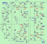
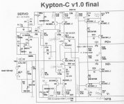
Good, that's what I used. I have attached a schematic with voltages. I'm not sure what is going on but hopefully one of you can see the issue. I have checked all of the devices and they are all correct and oriented properly.
BTW, this is hooked up to a small OPS so the NFB is connected to that.
Thanks, Terry
Attachments
Maybe you could try different opamps and report on how they effect output offset ?
Ive used LF411 on a different amplifier with good results.
I'm also interested what OS would use if he built the amp
Ive used LF411 on a different amplifier with good results.
I'm also interested what OS would use if he built the amp
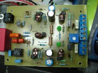
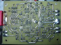
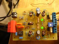
Some photos and measurements.
So then is yours working? I will check mine against yours.
Which BOM did you use? My resistors match the schematic you posted.
Thanks, Terry
Last edited:
Hi Terry ,yes mine is working.Just now i see that OS has change the zip.file R14,17 values are 68-82R,so i will change these values for lower VAS current.So then is yours working? I will check mine against yours.
Which BOM did you use? My resistors match the schematic you posted.
Thanks, Terry
Q5 ,Q6 in your board is on cut off. You haven't any voltage dropping at emiter resistors R12,13
Last edited:
Hi Jeff,
Good, that's what I used. I have attached a schematic with voltages. I'm not sure what is going on but hopefully one of you can see the issue. I have checked all of the devices and they are all correct and oriented properly.
BTW, this is hooked up to a small OPS so the NFB is connected to that.
Thanks, Terry
Looks to me like Q9 & Q10 may be swapped or the outputs are shorted together.
DOH! I just found the issue. I feel silly. On the screen shot, it shows the heatsink attached to the top of the transistor. I didn't pay attention to where the base pin was located. Let me flip those and get back to you. However, now the heatsink won't fit because the trimpot is in the way.
I see Thimios didn't use a heatsink. I wonder if they run cool enough to to not need it?
I see Thimios didn't use a heatsink. I wonder if they run cool enough to to not need it?
R10-13 (220R or 470R) will not affect idle current.
The feedback network (R14 -17)
can be 2.2k/82R or 1k / 39R.
With 1K/39R , increased current feedback needs more static bias current from the mirrors (R7 and R9) ... decrease to 8.2k.
If you don't have large resistors, R14-17 can also be 2.7k/100R . This
combo will work with R7/R9 at 10K , also.
To measure VAS current , calculate voltage drop across R25 ....subtract
from main VAS emitter R (R22 or R 27).
Terry , VAS semi's should be cool enough at 5ma to not need a heatsink.
OS
Maybe you could try different opamps and report on how they effect output offset ?
Ive used LF411 on a different amplifier with good results.
I'm also interested what OS would use if he built the amp
Tried LT1001 (like a TL0xx) , then a LT1022 (slightly better offset).
Since the op-amp here is not in any audio loop , it's performance just
affects offset AND PSRR. The "better" IC can raise PSRR by as much
as 10db.
Simply , this amp's CCS's are the op-amps internal sources ... the
servo functionality is a secondary "gift".
OS
Mine values for C10,C11 is 1000uf/16v .Any disadvantage from this?
C10/11 are just seeing millivolts. You could even use polarized ... positive
cap at Q1 , negative at Q2. 6.3v caps are even usable.
C10/11 can be 470-2200u / 6.3V - 25V. (junkbox) 😀
OS
Thanks Pete.🙂C10/11 are just seeing millivolts. You could even use polarized ... positive
cap at Q1 , negative at Q2. 6.3v caps are even usable.
C10/11 can be 470-2200u / 6.3V - 25V. (junkbox) 😀
OS
R10-13 (220R or 470R) will not affect idle current.
The feedback network (R14 -17)
can be 2.2k/82R or 1k / 39R.
With 1K/39R , increased current feedback needs more static bias current from the mirrors (R7 and R9) ... decrease to 8.2k.
If you don't have large resistors, R14-17 can also be 2.7k/100R . This
combo will work with R7/R9 at 10K , also.
To measure VAS current , calculate voltage drop across R25 ....subtract
from main VAS emitter R (R22 or R 27).
Terry , VAS semi's should be cool enough at 5ma to not need a heatsink.
OS
Hi Pete,
Showing that heatsink on the silkscreen is confusing since it is on the wrong side of the transistors. Either eliminate it or move the transistors over so you can fit it on the heatsink on the correct side.
Also, do you recommend making these latest changes to the resistor values or stick with the ones on the silkscreen?
Thanks, Terry
The "middle" values (82R/2.2K) seem to be the best compromise between
a cool resistor and sufficient low THD.
100R/2.7k = 12ppm
82R/2.2k = 8ppm
39R/1K = 5ppm
@ 1V input - 20K
When I move to the final stage ,I will flip those to-126's ...
OS
Those resistances are critical.
The most important for the quality of a CFA.
Changing the impedance of the feedback path, in an CFA, change both the bandwidth and the square waves behavior. So, it need to reconsider compensation at each change here.
Of course, we can think that an over-sized serial resistance, low noise, a-magnetic, with a flat temp coefficient is optimal.
But i often asked myself if we could not, with a resistance having a positive temp coefficient, and hot enough, compensate a little the losses of efficiency of speakers while the level increase, caused by the heat in their voice coil ?
On my side, looking for speed, i set their value at the point where the bandwidth don't increase any more, while their value decrease.
Last edited:
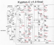
I got the one board working fine but the second one is giving me fits. I've noted the voltages on a schematic. I tested at +-35V because Q2 and the VAS devices are running very hot. NFB is tied to PD and ND through two 470R resistors so I can measure bias.
I have replaced Q2, Q7 & Q9. I've also checked every resistor and checked for shorts. Maybe a clue, D7 Doesn't light until I switch off power.
Hopefully one of you eagle eyes can spot the problem.
Thanks, Terry
I have replaced Q2, Q7 & Q9. I've also checked every resistor and checked for shorts. Maybe a clue, D7 Doesn't light until I switch off power.
Hopefully one of you eagle eyes can spot the problem.
Thanks, Terry
Attachments
I got the one board working fine but the second one is giving me fits. I've noted the voltages on a schematic. I tested at +-35V because Q2 and the VAS devices are running very hot. NFB is tied to PD and ND through two 470R resistors so I can measure bias.
I have replaced Q2, Q7 & Q9. I've also checked every resistor and checked for shorts. Maybe a clue, D7 Doesn't light until I switch off power.
Hopefully one of you eagle eyes can spot the problem.
Thanks, Terry
Are you sure D7 isn't installed backwards?
Yes I checked it with a 3v supply and a resistor. The weird thing is it lights about two seconds after I switch off the power and stays on until the PSU has drained down.
- Home
- Amplifiers
- Solid State
- Slewmaster - CFA vs. VFA "Rumble"