OK that makes sense. I'll start there in the morning. I never would have thought it would get hurt at such low voltages. The important thing is to keep learning..
Thanks, Terry
Thanks, Terry
I have trouble with this amp,i find extremely DC offset without dc servo,i take dc servo in apex ax17s from mr.mile.but every 3 minutes my amplifier have oscilation,
Hi Esperado,I have a working amplifier(post#4812)What is the recommend specific valu...s no more overshoot with little square waves.
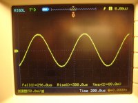
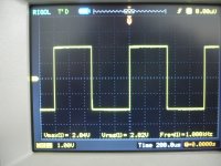
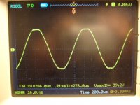
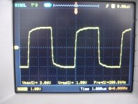
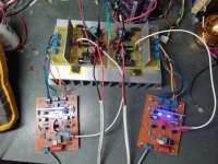
It's time for measurements
Please read on screens
Kypton-C V1.0
+/-50V
Idle cur.=70mA
Offset =1-2mV
All measurements on 7R dummy load.
Scopes prob at ampifier out (behind the coil)
Please read on screens
Kypton-C V1.0
+/-50V
Idle cur.=70mA
Offset =1-2mV
All measurements on 7R dummy load.
Scopes prob at ampifier out (behind the coil)
Attachments
-
 DSC08103.JPG548.8 KB · Views: 483
 -
 DSC08112.JPG531.6 KB · Views: 158
 -
 DSC08111.JPG608.6 KB · Views: 154
 -
 DSC08110.JPG597.6 KB · Views: 141
 -
 DSC08109.JPG539.2 KB · Views: 143
 -
 DSC08108.JPG563.3 KB · Views: 136
 -
 DSC08107.JPG571.4 KB · Views: 372
 -
 DSC08106.JPG563.7 KB · Views: 381
 -
 DSC08105.JPG592.2 KB · Views: 429
 -
 DSC08104.JPG584.9 KB · Views: 446
Last edited:
Please read on screens
Kypton-C V1.0
+/-50V
Idle cur.=70mA
Offset =1-2mV
All measurements on 7R dummy load.
Scopes prob at ampifier out (behind the coil)
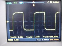
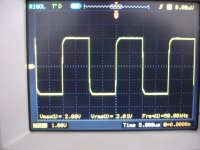
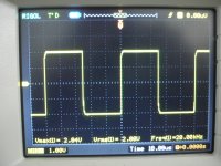
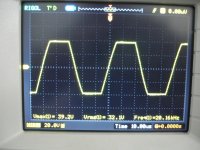
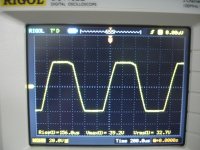
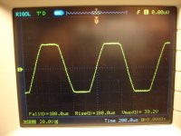
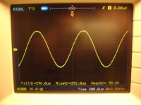
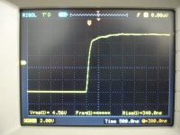
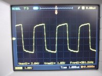
Excellent , not only did your static voltage readings match within mV's
but your clipping and squarewave tests match exactly , as well.
I just had to know whether the "self clamping" nature of the Baxandall
(super pair) was real. It IS !
Good servo action , too (1-2mv). It should sound superb and be very
reliable. 🙂
OS
But i don't understand the way for VAS current measurement .Please give me an arithmetical example.Suppose the voltage drop on R25/33K=36V(Mine vary from 36v up to 90v ,timer baced).
Last edited:
But i don't understand the way for VAS current measurement .Please give me an arithmetical example.Suppose the voltage drop on R25/33K=36V(Mine vary from 36v up to 90v ,timer baced).
For example - Ideal
.4V drop across r22 = .4/47 = .0085 = 8.5mA. This is the total I of the VAS.
146.4V drop across R24 and 25 (80V rails) 146.4 /58000 =.00252 = 2.52mA
Subtract 2.52 from 8.5 = 5.98ma .... that's what's "left over" for the cascode.
So ...the Led's use 2.52ma and the ksc3503/ksa1381 pair pass 5.98ma Ic.
You could calculate a "plain" Hawksford cascode in the same way.
Edit - if you wanted to drop vas output current 40K (R 24/25 total) 146/40000 =.00365
8.5 - 3.65ma = 4.85ma
OS
Last edited:
Thans .Now i understand the difficult way and the easy way of course.🙂10 R resistor across the PD+ from IPS - OPS
.06V/10 = .006 =6ma 🙂
os
Excellent , not only did your static voltage readings match within mV's
but your clipping and squarewave tests match exactly , as well.
I just had to know whether the "self clamping" nature of the Baxandall
(super pair) was real. It IS !
Good servo action , too (1-2mv). It should sound superb and be very
reliable. 🙂
OS
Now it is confirmed that my suggestion to use Baxandall super pair VAS to get good clipping is not only simulation artifact, thank you thimios and to OS too.
Damir
I'm here to test everything.(all your suggestions)🙂Now it is confirmed that my suggestion to use Baxandall super pair VAS to get good clipping is not only simulation artifact, thank you thimios and to OS too.
Damir
Thimios.
CFA-fast VFA... Very cool! 
Ah... Kypton-C is a CFA one... sorry... mixed up
Cool anyway 🙂 I'm sure Kypton-V will be rather close in terms of speed.
Ah... Kypton-C is a CFA one... sorry... mixed up
Cool anyway 🙂 I'm sure Kypton-V will be rather close in terms of speed.
Last edited:
Hi Terry,
I have looked at you voltage readings in post #4826. If I got these measurements I would check for high frequency oscillation. A digital voltmeter is likely to give voltage readings that nonsense if there is high frequency oscillation present at the points where you are measuring.
Do you have access to a oscilloscope? If not, since this is relative low voltage, you could try to touch the point of measurement with your finger while doing the measurement to see if this have any effect.
I might be wrong and some of your voltage readings seem fine, but it would be my first thought.
Mogens
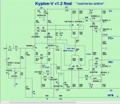
"V" is next - another "supperpair"
I went with your 2'nd stage for the "V" "vzaichenko edition" (Below 1). 😉
Thank you , brother !
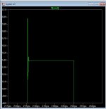
As far as speed , I "throttled" it at 150V/uS. Why ? (below 2).
This topology has the gain margin extension at 20-40K ... massive gain.
But this gain makes for good ringing ... that "dip" in the phase response
(20k-100k)correlates to the amp "choking" on them squarewaves.
Cordell used the same local feedback (R38/C7) in his HEC paper
to tame the beast.
So , the tradeoff is 12ppm 20K ,150V slew , and a 1mhz unity gain point.
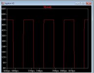
But , I have 90+ db phase margin (really rock solid) and
it "eats" square waves (below 3 - with 6.8p C7).
OS
CFA-fast VFA... Very cool!
Ah... Kypton-C is a CFA one... sorry... mixed up
Cool anyway 🙂 I'm sure Kypton-V will be rather close in terms of speed.
I went with your 2'nd stage for the "V" "vzaichenko edition" (Below 1). 😉
Thank you , brother !
As far as speed , I "throttled" it at 150V/uS. Why ? (below 2).
This topology has the gain margin extension at 20-40K ... massive gain.
But this gain makes for good ringing ... that "dip" in the phase response
(20k-100k)correlates to the amp "choking" on them squarewaves.
Cordell used the same local feedback (R38/C7) in his HEC paper
to tame the beast.
So , the tradeoff is 12ppm 20K ,150V slew , and a 1mhz unity gain point.
But , I have 90+ db phase margin (really rock solid) and
it "eats" square waves (below 3 - with 6.8p C7).
OS
Attachments
I deliberately did not answer the previous question, but I agree with your choice 😉
Local feedback is a cool solution. In my hybrid I've got the unity gain point at 1.5MHz and the "dip" in phase response is rather light, so I have left it "as is".
Congratulations brother - another great front-end!
Local feedback is a cool solution. In my hybrid I've got the unity gain point at 1.5MHz and the "dip" in phase response is rather light, so I have left it "as is".
Congratulations brother - another great front-end!
Almost worth slugging it out and finding what's wrong. This is weird. I'm still a firm believer in breaking it down into smaller sections and zeroing in that way. That's why I suggested lifting legs on R14 & 17.
Hey Jeff,
Good advice. I lifted R14 and R17 and disconnected the NFB but still had 34V on the emmitters of Q1&Q2. That could only mean one thing. Somehow the rail was getting onto the NFB. So I scoured the foil side again and I found a solder bridge the size of hair between the pad for R4 and the positive rail trace going to Q2. A little scratch with a probe tip and wa-la fixed. I put everything back together and It has been playing sweet music for a couple hours now. Sounds lovely. I have it playing through my Mini OPS right now. When I get a chance to hook it up to a slewmaster OPS I will attach the scope and get some shots of it playing square waves for your enjoyment. 😀
Attachments
Hey Jeff,
Good advice. I lifted R14 and R17 and disconnected the NFB but still had 34V on the emmitters of Q1&Q2. That could only mean one thing. Somehow the rail was getting onto the NFB. So I scoured the foil side again and I found a solder bridge the size of hair between the pad for R4 and the positive rail trace going to Q2. A little scratch with a probe tip and wa-la fixed. I put everything back together and It has been playing sweet music for a couple hours now. Sounds lovely. I have it playing through my Mini OPS right now. When I get a chance to hook it up to a slewmaster OPS I will attach the scope and get some shots of it playing square waves for your enjoyment. 😀
Good to hear! My theory of breaking things down into sections when troubleshooting applies to just about anything. I hate just blindly throwing parts at it. It also forces you to learn the operation of everything quickly too.😀
ostripper
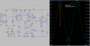
Sory for small offtpic. I would be very happy If You will can help me a bit.
I am trying to do my first hybrid and i do not know how to ged rid of the crossover distortions spikes (I am not sure about it) in the input stage. There seems to be nothing bad happening in output stage but two front LTP currents arent looking good.
*.asc file is in zip.
Big thanks.
Peter
Attachments
- Home
- Amplifiers
- Solid State
- Slewmaster - CFA vs. VFA "Rumble"