Separate Higher Power Suppy for the input stage
Has anyone tried using a higher and separate supply for each of the input sections? This was used in the Gouldmund and it's clone. Since the input section is a separate PCB, how much better would they sound with this change? Just an idea?😉
Has anyone tried using a higher and separate supply for each of the input sections? This was used in the Gouldmund and it's clone. Since the input section is a separate PCB, how much better would they sound with this change? Just an idea?😉
I understood that to be the purpose of the cap multiplier, though it doesn't provide higher voltage, just cleaner.
The ability to use boosted rails for the driver and IPS stages is a part of the design. I don't know if anyone has tried it yet. I have been playing with a voltage doubler / capacitance multiplier based supply in simulation to give ~12V boost to the main rails.
It depends what you mean by separate supply and to what end it would work towards.
The CF amps with the hawksford VAS lose a certain amount of voltage headroom and using a separate input stage supply, that runs a few volts higher than the main supply, would circumvent this and allow you to reach the full voltage swing of the output stage. Whether or not this is necessary with amplifiers running on 70-80 volt rails is another matter entirely.
It is also possible that the rise in HD3 that I see, when running the amplifiers closer to the power rails, could be mitigated entirely by running the IPS from say +-40 volts vs the +-25 on the output stage.
Most of the amplifiers here have appreciable PSRR and do not need a separate supply to meet performance criteria. Nevertheless the CF amps do benefit from some sort of regulation to the input stage as OS originally included zener regulation for the input pair to this end. One can do this without a 'separate' supply as the input pair do not need the ability to swing many volts, you can just regulate a spur off of the main supply.
As far as I know the only real reason to use a separate higher voltage supply, is if the use of the same voltage throughout the amplifier actually causes the amplifier to clip due to voltage limitations on the input stage.
If it doesn't then you're doing it for performance gains by increasing supply rejection. As far as I am aware most LTPs work with a current output and can be regulated at a few volts lower than the main supply without limiting the output swing of the amplifier, which leaves only the VAS operating from the same raw supply as the OPS.
I suppose one could argue, if you want an amplifier that can swing +-50 volts and you're going to lose +-5 volts due to the nature of the input stage, then why not use a single supply rated at +-60 volts? Feed that directly to the output stage, then regulate it down to +-55 volts and feed that to the input stage.
This way you only need to use one supply, you get your improved PSRR by regulating the input stage's power supply and you end up with an amplifier that can swing the number of volts that you want.
Hello,
I encountered a weird problem when assembling the amplifier into the case (cfa-x + baby ops). In the beginning everything went fine but when I connect rca cables into the input I get 25mV 50hz hum. When nothing is connected to the input or the input wires are very short (say 20cm) the amp is completely silent with 0.8mV ac at the output.
I have checked the grounding scheme about a dozen times and it should be correct and I am assuming the the origin of hum is somewhere else.
It seems that the cable is somehow collecting noise but I do not understand how this can happen. I have moved the amp away from assumingly noisy environment, tried to move the wires around, use different cables etc.
When I touch the amp case eith my finger the amount of hum is about halved.
I have no further ideas what to do.
Does anyone have any idea what is going on?
J
Last edited:
Obviously not. Ground loop, at evidence.I have checked the grounding scheme ...
I am assuming the the origin of hum is somewhere else.
Can-you publish your cabling schematic (with power supply and AC+audio) ?
Last edited:
Hello Esperado.
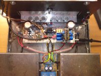
Please find the attached picture.
both PCB grounds and speaker grounds lead to single point in the middle of the supply caps except the rca ground which is connected to the signal ground at the ips board.
The trafo is center tap model. The ct is connected to the main star.
The main star is connected to the case through a ground lifter consisting of a bridge rectifier and 10 ohm resistor.
Too lazy to draw an illustration. I hope that the pic is clear enough.
J
Attachments
Mistake common to nearly all IPS schematics I saw here is feedback resistor (ground arm)connected to power ground ..It should be connected to input signal ground, to the same point as input bias resistor and input ground from signal source.
Last edited:
Mistake common to nearly all IPS schematics I saw here is feedback resistor (ground arm)connected to power ground ..It should be connected to input signal ground, to the same point as input bias resistor and input ground from signal source.
I just looked through the IPS schematics that I have from this thread and I don't see where you changed anything in regards to the ground in the IPS that you published. Would you please post a schematic showing what you are referring to?
I haven't had a problem with any of the ones I've built so far. CFA 3 versions, Spooky and Wolverine.
Thanks, Terry
This is how you need to wire up an amp internally to kill internal and externally created ground loops. The high quality and dirty grounds should not be connected on the PCB at any point. Wired up as shown you do not need the 10R isolation resistor on the input stage either. Simply connect all G2 points to the same place and connected the shielded input wire to it as shown.
Attachments

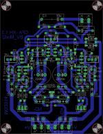
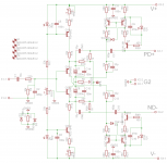
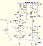
Some progress under eagle : as i didn't found CFA-XH 1.3 IPS in BV mod2 i decided to transfert schematic under eagle and do routing job. See under...if you have advise feel aware and post...
Attachments
Last edited:
Hi maybe this help a lot members from a nice person member BONSAI
Attachments
Last edited:
Why not use of fet for drive output, for example type 2SK213 and 2SJ76 they are fast,and
uses by Accuphase for example E 210 amp,
Alcroner
uses by Accuphase for example E 210 amp,
Alcroner
The ratio of R28 and R29 sets the gain. Check the values and adjust R29 if needed. R2 and R28 should be the same to help achieve low DC offset.
I think separate transformers for input and for drive/ outputstage is good idea even
and low impedance regulators for input stages perhaps type of shunt regulators.
Alcroner
and low impedance regulators for input stages perhaps type of shunt regulators.
Alcroner
I think separate transformers for input and for drive/ outputstage is good idea even
and low impedance regulators for input stages perhaps type of shunt regulators.
Alcroner
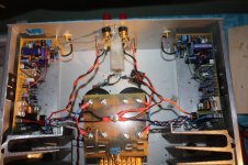
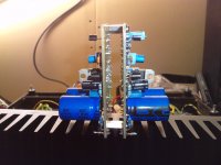
My front end supply.

Attachments
Not really.Too lazy to draw an illustration. I hope that the pic is clear enough.
May-be you can find your inspiration here: http://www.diyaudio.com/forums/vend...e-mosfet-amplifier-module-42.html#post3940983
One thing is for sure, as a general law: ground of the speakers+ground of the power supply arrival on the circuit boards are to be at the same point (on the board). As well, with a separated wire/circuit track, than the ground of the feedback bridge.
Before to connect the input wires, find the AC sens witch gives the less voltage between the input ground and the ground of the input wires.
Well, there are different solutions, according the way the boards are designed. Just think all the ground tracks/wires as if they were resistances.
Last edited:
The ratio of R28 and R29 sets the gain. Check the values and adjust R29 if needed. R2 and R28 should be the same to help achieve low DC offset.
Thanks Jason. That worked. serves me right for only building one side first. I had too many schematics. One had 15k for R25 and the other had 22k. Switched to 15k in both and now all is good.
Thanks.
- Home
- Amplifiers
- Solid State
- Slewmaster - CFA vs. VFA "Rumble"