Symasui Re-draw
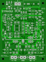
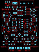
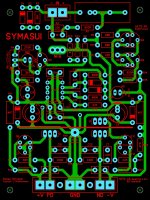
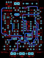
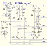
Here's my current rendition of the Symasui v1.2 board. It should be accurate but if anyone is so inclined to have a look over it to spot any potential errors that would be great. Any constructive comments / concerns welcomed.
Here's my current rendition of the Symasui v1.2 board. It should be accurate but if anyone is so inclined to have a look over it to spot any potential errors that would be great. Any constructive comments / concerns welcomed.
Attachments
Looks good Jason but two servo circuits and a NFB circuit, that should be fun to get everything right.
Looks good Jason but two servo circuits and a NFB circuit, that should be fun to get everything right.
Not too sure what you mean. There is only one servo, it has two pole response. NFB of course is mandatory with the design's OLG. This is ostripper's circuit, just my spin on the PCB.
where is the like button?😀
accurate maybe asking too much...
for me i am content when my amps do not hum, do not hiss, sound consistent at low volumes as well as high volume levels(below clipping) and above all is not tiring to listen to...my expectations are modest, no?😉
accurate sound is my wish, it give me motivation to learn...
now i can design an amp that "do not hum, do not hiss, sound consistent at low volumes as well as high volume levels(below clipping)"
Jason,
I guess I am just not following how the servo feed and servo return are two poles? That is why you are the circuit designer and I'm not.
I guess I am just not following how the servo feed and servo return are two poles? That is why you are the circuit designer and I'm not.
That is the same servo that is in the Spooky I just finished. Once everyone got me straightened out on how it works, it keeps the offset very stable.
Hi to All,
Yesterday i finished to read the whole 341pages, this achieve to made me want to go foward in slewmaster way. Slewmaster versatility through IPS change is a really nice feature. Last pas month i played with TSSA and VSSA and some other iteration on these. VSSA and his Borys BJT_ouput version gave lot of pleasure during lisen session. The next amp i want to built mus have more power and current avalaibility since i plane to build more asking speakers as they i have today. The goal is to build an amp that wont limit me in speaker exploration in my 15m² listen room. So no need of 300W at 8Ohm. I think 100W/8r, 200W/4R and stability at 3-2ohm will be plenty sufficient.
So After reading whole thread here what i scale for my build
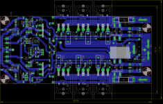
OPS : SLEMASTER => 3 BJT output pair (I have good matced ONSEMI MJL3281/1302 triplet), drived by NJW0281/0302. These as KSA1381/KSC3503 and KSA1220A-Y/KSC2690A-Y are already in stock.
IPS : for sure test VSSA iteration, but spooky to and maybe wolverine.
For power supply i have two heavy (6.5kg each) 500VA 2x36Vac Rcore Trafo. These will give me around +/-50Vdc rail with nice margin for low impedance ask.
For Slewmaster dissipation i have already two nice 265x140x75mm (16mm substrate).
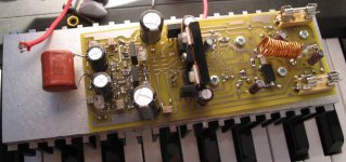
Last evening i take some time to convert schematic under eagle and achieve layout (joint picture). It's OS clone as he has do grate quality job. So i am able to etch at home my board. So next step is to do same with different IPS.
Yesterday i finished to read the whole 341pages, this achieve to made me want to go foward in slewmaster way. Slewmaster versatility through IPS change is a really nice feature. Last pas month i played with TSSA and VSSA and some other iteration on these. VSSA and his Borys BJT_ouput version gave lot of pleasure during lisen session. The next amp i want to built mus have more power and current avalaibility since i plane to build more asking speakers as they i have today. The goal is to build an amp that wont limit me in speaker exploration in my 15m² listen room. So no need of 300W at 8Ohm. I think 100W/8r, 200W/4R and stability at 3-2ohm will be plenty sufficient.
So After reading whole thread here what i scale for my build
OPS : SLEMASTER => 3 BJT output pair (I have good matced ONSEMI MJL3281/1302 triplet), drived by NJW0281/0302. These as KSA1381/KSC3503 and KSA1220A-Y/KSC2690A-Y are already in stock.
IPS : for sure test VSSA iteration, but spooky to and maybe wolverine.
For power supply i have two heavy (6.5kg each) 500VA 2x36Vac Rcore Trafo. These will give me around +/-50Vdc rail with nice margin for low impedance ask.
For Slewmaster dissipation i have already two nice 265x140x75mm (16mm substrate).
Last evening i take some time to convert schematic under eagle and achieve layout (joint picture). It's OS clone as he has do grate quality job. So i am able to etch at home my board. So next step is to do same with different IPS.
Attachments
Just be aware that mounting the OPS vbe bias tracking transistor directly to one of the output transistors will give you much better thermal tracking than with it miles away, like you've got. Of course that's just the PCB design and you could mount it quite easily with flying leads elsewhere. I'm just pointing this out in case you want to do that and would design the PCB slightly differently otherwise.
Just be aware that mounting the OPS vbe bias tracking transistor directly to one of the output transistors will give you much better thermal tracking than with it miles away, like you've got. Of course that's just the PCB design and you could mount it quite easily with flying leads elsewhere. I'm just pointing this out in case you want to do that and would design the PCB slightly differently otherwise.
I read your advice before but I OS seems to say that not optimal do extra wire length....Two configurations are doable...
Marc
As to the vbe bias resistor, I was under the impression that it is mainly used as diodes and the flying wires don't affect the audio. I can attest that the thermal control is a little lacking in the stock form. I haven't tried flying it yet on wires so I can't say if that fixes it but setting the bias takes a bit more work than I would prefer. I have to pull one of the OPS to fix the Cap multiplier so I will try moving that transistor to the top of the nearest output at that time and see if it helps or hurts anything. I'll try to get to the this week so I can let you know.
Blessings, Terry
Blessings, Terry
Yes I did, that is, of the blameless amp and Bob Cordell's HEC amp. Simulated THD20k figures were very close (+/- 10%) to real values.yes, Terry go ahead and test.....and tell us what you find....😉 has anyone here made a correlation between simulations and actual testing on built amps?
what was the result? how close was the simulation to the real thing?
Cheers, E.
Some can like very distorted amps...
Like: VOX AC30, Fender Custom, Marshall 2061X etc...
😀
And this is often... the beginning :
https://www.youtube.com/watch?v=m9N8Qi6zLSU
https://www.youtube.com/watch?v=TLV4_xaYynY
🙂
I've never understood why people like the extreme distorted sound of Jimi Hendrix (I detest it, way too aggressive). OTOH, this kind of distortion (Eric Clapton & George Harrison, RIP): https://www.youtube.com/watch?v=oDs2Bkq6UU4 sounds more friendly.
Cheers, E.
Almost no distortion there at all. Mostly Chorus/phase shifting.I've never understood why people like the extreme distorted sound of Jimi Hendrix (I detest it, way too aggressive). OTOH, this kind of distortion (Eric Clapton & George Harrison, RIP): https://www.youtube.com/watch?v=oDs2Bkq6UU4 sounds more friendly.
Cheers, E.
With regards to simulated and measured THD, I can only echo what Edmond has said, except just to add one thing. When you get into the ridiculously low levels of distortion, the 5ppm at 10k type stuff, it is not to be taken lightly. This level of distortion is very low and requires good hardware for you to be able to measure it correctly.
Adding to this is that the distortion mechanisms, as detailed by Self, get more troublesome to deal with the greater the performance of the amplifier. For example if your amplifier only has 0.01% THD at 10k, then you can really slack off with some things, whereas if it should really be 0.0005% you cannot afford this luxury.
Most of the distortion types are easily dealt with, but one, induction based distortion, is quite a different matter. It gets harder to eliminate as output powers rise and it does more harm at high frequencies too. The reason why THD20 and THD10 figures are being quoted here is because the high frequency performance of the amplifier pretty much details how good a design it is.
Your simulator might say you should see 0.0005% at 10k, but unless your implementation is really top notch then you're not going to see this. You might say this is down to simulation error vs real world, but in fact it is not. The amplifier is capable, it's just your implementation could be improved.
Okay so here we have the next instalment.
The CFA-XH BV2.

This is NOT the board that used the ground plane. I repeat NOT, the board that used the ground plane. That board seriously failed and suffered from TERRIBLE, I repeat TERRIBLE, induced distortion. Why this was so I don't really know as the high quality and dirty grounds were still separated. So here's your warning, do not bother with a ground plane type design for a power amplifier. It is not needed and all it does is give you a headache. If you don't have the capabilities to measure what you're doing properly then there's more reason to simply stick to what we know works.
 NO GROUND PLANES!
Just so no one misses it!
This board uses LM337/317 regulation for the input stage and does not use the standard 992/1845 for the input pair either. As I posted before I had an idea to use the BC846BPN. This is a tiny little surface mount device that has both an NPN and PNP transistor combined, presumably built from the same wafer so promises to give you a good transistor match and obviously provides excellent thermal matching. NXP provide excellent simulation models for these and using them gives excellent results, better than the 992/1845s with my set up.
Once again this is the baby OPS, using two output pairs, this time 1943/5200s. The amplifiers are run from nominally ~26V supplies as I intend to use them mostly biased into class A.
First of all 2.83V RMS into 9.4 ohms optimally biased.

Pretty good, but somewhat high HD2.
Now the same as above but in class A.

If anyone wanted the proverbial straight wire with gain for the first watt, this would probably be quite close to it. 😀
As I mentioned in my previous post, measuring distortion at these kinds of levels is a trial in and of itself. I am sure that the HD2 vanishes in this case simply because biasing into class A removes any rail induction distortion. I can bring about quite dramatic changes in the distortion by moving the various wires around. Quite clearly these need to be positioned optimally to give the best results. The amplifier is currently a heatsink on board and not in any kind of case so I didn't want to mess about too much with it. This was more a proof of design before I build three more, but when put into the proper case I will take time routing the wires in a more optimal fashion.
Next up is 7V RMS into the 9.4 ohm loas optimally biased.

It looks fairly similar to before.
And now in class A.

Once again, the first thing to note is that the HD2 just takes a vacation again. At an increased output power the SnR has increased and we can also see a small reduction in the magnitude of the higher order harmonics at high frequencies. This is what class A biasing is all about. We can also see the marked increase in the third order too. It's still objectively very low 0.001% @ 10k. Why this occurs I don't know, but it did it with my very first CFA-XH BV2 board also.
Still it's nothing to really lose any sleep over, it's still very low distortion.
Next up is the amplifier just before clipping occurs so around 13.5V RMS optimally biased.

Here we can see that the HD3 has shot up, although absolute levels aren't excessively high.
Now into class A.

Once again HD2 drops, as do the higher harmonics, but the HD3 increases again at high frequencies.
Regardless of the amplifiers possibly odd behaviour with the third order, this version does appear to measure a little better than the previous one. Regardless of that though I am pretty pleased with how this turned out. The BC846BPN certainly works well and they cost peanuts.
One thing I will mention again is just how sensitive this design is to getting the bias level spot on. If you under bias it a little, distortion, and most importantly, higher order distortion, shoots way up. If you over bias it the exact same thing happens too, but not as badly. When you reach class A all the over biasing nasties suddenly vanish.
This is mainly a comment towards thimios. I know you had some 'differences' in sound quality of what this amp did not and the others did. It might be worth trying this amplifier again, but before listening adjust the bias first with the amp connected to the FFT on the computer. I know your hardware isn't as capable as mine, but you should still be able to arrive at a more optimal bias setting I think, even with what you've got.
You are definitely better off over biasing the amplifier slightly though, than under biasing. Under biasing is a disaster and you lose anything and everything that the amplifier is capable of and all you'd be listening to is output stage nasties instead of what the input stage might be able to do.
I didn't give a subjective impression of the Wolverine simply because it's operating from only 50Hz-300Hz with multiple subs operating from 20Hz up to 100Hz over the top of that too. Whatever it's doing it's doing it well, but it's not the kind of thing you can get particularly excited or articulate about. The quad of CFA-XH BV2s will be used from 300Hz to 20kHz, so I will be certain to say something about that.
The CFA-XH BV2.
This is NOT the board that used the ground plane. I repeat NOT, the board that used the ground plane. That board seriously failed and suffered from TERRIBLE, I repeat TERRIBLE, induced distortion. Why this was so I don't really know as the high quality and dirty grounds were still separated. So here's your warning, do not bother with a ground plane type design for a power amplifier. It is not needed and all it does is give you a headache. If you don't have the capabilities to measure what you're doing properly then there's more reason to simply stick to what we know works.
NO GROUND PLANES!Just so no one misses it!
This board uses LM337/317 regulation for the input stage and does not use the standard 992/1845 for the input pair either. As I posted before I had an idea to use the BC846BPN. This is a tiny little surface mount device that has both an NPN and PNP transistor combined, presumably built from the same wafer so promises to give you a good transistor match and obviously provides excellent thermal matching. NXP provide excellent simulation models for these and using them gives excellent results, better than the 992/1845s with my set up.
Once again this is the baby OPS, using two output pairs, this time 1943/5200s. The amplifiers are run from nominally ~26V supplies as I intend to use them mostly biased into class A.
First of all 2.83V RMS into 9.4 ohms optimally biased.
Pretty good, but somewhat high HD2.
Now the same as above but in class A.
If anyone wanted the proverbial straight wire with gain for the first watt, this would probably be quite close to it. 😀
As I mentioned in my previous post, measuring distortion at these kinds of levels is a trial in and of itself. I am sure that the HD2 vanishes in this case simply because biasing into class A removes any rail induction distortion. I can bring about quite dramatic changes in the distortion by moving the various wires around. Quite clearly these need to be positioned optimally to give the best results. The amplifier is currently a heatsink on board and not in any kind of case so I didn't want to mess about too much with it. This was more a proof of design before I build three more, but when put into the proper case I will take time routing the wires in a more optimal fashion.
Next up is 7V RMS into the 9.4 ohm loas optimally biased.
It looks fairly similar to before.
And now in class A.
Once again, the first thing to note is that the HD2 just takes a vacation again. At an increased output power the SnR has increased and we can also see a small reduction in the magnitude of the higher order harmonics at high frequencies. This is what class A biasing is all about. We can also see the marked increase in the third order too. It's still objectively very low 0.001% @ 10k. Why this occurs I don't know, but it did it with my very first CFA-XH BV2 board also.
Still it's nothing to really lose any sleep over, it's still very low distortion.
Next up is the amplifier just before clipping occurs so around 13.5V RMS optimally biased.
Here we can see that the HD3 has shot up, although absolute levels aren't excessively high.
Now into class A.
Once again HD2 drops, as do the higher harmonics, but the HD3 increases again at high frequencies.
Regardless of the amplifiers possibly odd behaviour with the third order, this version does appear to measure a little better than the previous one. Regardless of that though I am pretty pleased with how this turned out. The BC846BPN certainly works well and they cost peanuts.
One thing I will mention again is just how sensitive this design is to getting the bias level spot on. If you under bias it a little, distortion, and most importantly, higher order distortion, shoots way up. If you over bias it the exact same thing happens too, but not as badly. When you reach class A all the over biasing nasties suddenly vanish.
This is mainly a comment towards thimios. I know you had some 'differences' in sound quality of what this amp did not and the others did. It might be worth trying this amplifier again, but before listening adjust the bias first with the amp connected to the FFT on the computer. I know your hardware isn't as capable as mine, but you should still be able to arrive at a more optimal bias setting I think, even with what you've got.
You are definitely better off over biasing the amplifier slightly though, than under biasing. Under biasing is a disaster and you lose anything and everything that the amplifier is capable of and all you'd be listening to is output stage nasties instead of what the input stage might be able to do.
I didn't give a subjective impression of the Wolverine simply because it's operating from only 50Hz-300Hz with multiple subs operating from 20Hz up to 100Hz over the top of that too. Whatever it's doing it's doing it well, but it's not the kind of thing you can get particularly excited or articulate about. The quad of CFA-XH BV2s will be used from 300Hz to 20kHz, so I will be certain to say something about that.
Attachments
-
 13.5vrms 9.4 ohm load optimally biased.GIF148.4 KB · Views: 714
 -
 7vrms 9.4 ohm load CA.GIF158.5 KB · Views: 703
 -
 7vrms 9.4 ohm load optimally biased.GIF153 KB · Views: 722
 -
 2.83 vrms 9.4 ohm load ClassA.GIF154.1 KB · Views: 727
 -
 2.83 vrms 9.4 ohm load optimally biased.GIF159.7 KB · Views: 773
 -
 CFA.jpg99.8 KB · Views: 772
 -
 13.5vrms 9.4 ohm load CA.GIF155.6 KB · Views: 713
Yes I did, that is, of the blameless amp and Bob Cordell's HEC amp. Simulated THD20k figures were very close (+/- 10%) to real values.
Cheers, E.
thanks, this is all i want the hear....
Edmond, if you listen carefully, it is not the distortion of the guitars of Hendrix witch are disagreeable, but the recording witch is distorted. Specially the rhythmic guitar.the extreme distorted sound of Jimi Hendrix
A little like the stones, you know ? Mick Jagger said one time that they tried hard at their beginning to have a clean sound like the Beatles. Amusing, as their dirty sound made all their success and magic 🙂
Edmond, if you listen carefully, it is not the distortion of the guitars of Hendrix witch are disagreeable, but the recording witch is distorted. Specially the rhythmic guitar.
A little like the stones, you know ? Mick Jagger said one time that they tried hard at their beginning to have a clean sound like the Beatles. Amusing, as their dirty sound made all their success and magic 🙂
I always thought that what made the Stones so popular was that their songs were so crude and simple that every garage band in the world could pull them off. 😎
Jimi Hendrix sound
You must have golden ears to distinguish between the distortion of his guitar amp and the distorion of the rest of the (studio) gear. Anyhow, it sounds like a heavely overloaded ill biased cheap underpowered transistorized class-B amp.
Cheers, E.
Hi Christophe,Edmond, if you listen carefully, it is not the distortion of the guitars of Hendrix witch are disagreeable, but the recording witch is distorted.
[snip]
You must have golden ears to distinguish between the distortion of his guitar amp and the distorion of the rest of the (studio) gear. Anyhow, it sounds like a heavely overloaded ill biased cheap underpowered transistorized class-B amp.
Cheers, E.
Indeed. For those of us who listened to the original Beatles, Stones etc...at the radio, or, during surprise parties, on their little radio phono combo, it is very disappointing to listen today their remastered CD on a high end hifi equipment. With lost intermodulation and other distortions, a lot of fun and mystery, or atmosphere, flew away. You know, the "wall of sound" ;-)I always thought that what made the Stones so popular was that their songs were so crude and simple that every garage band in the world could pull them off. 😎
Oh, no, just i had spend too many years to fight in various studio against their poor (and expensive) equipment ;-)You must have golden ears to distinguish between the distortion of his guitar amp and the distorion of the rest of the (studio) gear.
Last edited:
- Home
- Amplifiers
- Solid State
- Slewmaster - CFA vs. VFA "Rumble"