I would think you would need to use 100V caps with that rail voltage to stay out of trouble?
Thank you
So these is sure even C107.........
C105 & C102 22uF V???
C103 & 106 220uF V rating ??
These are from rail to ground. 100V minimum.
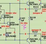
C107 1uF 50V to my 80VDC supply is OK?
This one sees less than 6V so 25v is plenty.
C103 & 106 220uF V rating ??
These are from rail to ground. 100V minimum.
C107 1uF 50V to my 80VDC supply is OK?
This one sees less than 6V so 25v is plenty.
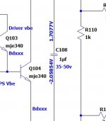
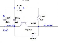
Here are the voltages as seen in Ltspice with +-81V rails. My file calls C107 as C108 because that it was changed to C107 in the last rendition. You can see that C107 sees less than 4Vdc. The cap multiplier sees almost full rail.
Attachments
Last edited:
Yes I need 100V caps everywhere accept C108 (on your diagram) where 35V will be enough
The reason I asked I do not want to order wrong (lower) V caps, also I need to pay att. some boutique caps are oversized.
Thank you one more time
The reason I asked I do not want to order wrong (lower) V caps, also I need to pay att. some boutique caps are oversized.
Thank you one more time
Your simulated bias current is about 4mA, try using a lower value set of resistors like 8K2 or 7K5 in place of the 10K to increase the mock IPS current a little. You likely just don't have enough current flow to get the bias circuit to turn on.
When you put an ammeter across (in parallel) the resistor you short it out and the current goes way up because now there is only one resistor in the mock IPS circuit. The meter, when in current or ammeter mode, must be in series with what you are measuring. With a known resistance you only need the voltage across the resistor and ohms law to know the current 😉.
Hi Jason, tried 7k5 across mocked resistor- not biasing, even hooked up with wolverine IPS -not biasing either.
Quan
Hi quan,
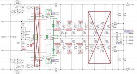
I don't think R110 is supposed to be there when using MOSFETs. That 1K would be shunting the bias generator. Remove R110 and see if that gets the bias generator up.
I don't think R110 is supposed to be there when using MOSFETs. That 1K would be shunting the bias generator. Remove R110 and see if that gets the bias generator up.
Hi quan,
I don't think R110 is supposed to be there when using MOSFETs. That 1K would be shunting the bias generator. Remove R110 and see if that gets the bias generator up.
Hi Jason, i got confused with the new schematic as it looks as though r110 should be left in place. And with the Mosfet schematic that Evan posted it looks as though there are 2 parrallel 1K resistors in place of c114?. Just another question, i have mje15032/15033 currently installed. Would these TO220 devices ok to drive 5Mosfets pairs?
Quan
Last edited:
Yes, I noticed when I went and looked at OS's last schematic that he made no notation to the fact that R110 would be an 'Option A' BJT OPS component and that for 'Option B' it should have been omitted. The schematic Evan re-posted is a modified one that vzaichenko posted when we were first tinkering with MOSFETs on the original boards.
R113 can be lower if you want to operate the drivers with a higher standing current, I'd say down to 470R would be no issue. C114 can stay as specified, no issue that I'm aware of.
The TO-220 devices should drive the MOSFETs just fine. The MOSFETs only draw current at high frequencies to drive the gate capacitance.
Lost my isp. No isp available
At any price. Must move to a
City soon..
Mid sept. Most likely. I am
As well or better with no internet
Os
At any price. Must move to a
City soon..
Mid sept. Most likely. I am
As well or better with no internet
Os
Lost my isp. No isp available
At any price. Must move to a
City soon..
Mid sept. Most likely. I am
As well or better with no internet
Os
Good to here all is well. I think I'd have an easier time going without indoor plumbing than internet though.🙁
Yes, I noticed when I went and looked at OS's last schematic that he made no notation to the fact that R110 would be an 'Option A' BJT OPS component and that for 'Option B' it should have been omitted. The schematic Evan re-posted is a modified one that vzaichenko posted when we were first tinkering with MOSFETs on the original boards.
R113 can be lower if you want to operate the drivers with a higher standing current, I'd say down to 470R would be no issue. C114 can stay as specified, no issue that I'm aware of.
The TO-220 devices should drive the MOSFETs just fine. The MOSFETs only draw current at high frequencies to drive the gate capacitance.
OK then, i will omit C114, leave r113 as 1K 1W and pulled out r 110 later and report back then.
Quan
Hi Pete welcome back!🙂🙂🙂Lost my isp. No isp available
At any price. Must move to a
City soon..
Mid sept. Most likely. I am
As well or better with no internet
Os
- Home
- Amplifiers
- Solid State
- SlewMaster Builds