Hi guys, running into a bit of trouble. Spooky IPS D8 is not lighting up?. Any advice where to start trouble shoot?. Also when i tried to measured R28 or R29 current then the LED light up?. My other board D7 is not on either?.
Quan
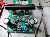
Hi Guys, all good now with Spooky IPS. It turns out that i stuffed up with npn pairs but all ok now. My attention turned to SlewFET which is not running even though the circuit is so simple. The red LED not light up and no current passed thru the R111/112. Any comment guys.
a few other voltage measurements r107=0.334V, r105=0.595, r104=0.6v, r103=1.545v,r110=3.312v,r113=2.18v, D102=0.545V.
Quan
Attachments
Last edited:
Have you verified your 'dummy IPS' resistors are passing ~5mA, give or take? If the value is too high for your test supply you won't get enough current to get the bias spreader fully up.
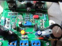
small progress...I hope , that I already correct all my errors...
You shouldn't have the LED in above Q104. It should be jumpered out. You may need bigger drivers for 3 output pairs too. I thin TO220 is only good for 2 pairs of outputs. I posted a schematic with a little clearer explanation of parts needed for different versions here. http://www.diyaudio.com/forums/solid-state/260268-slewmaster-builds-109.html#post4422418
small progress...I hope , that I already correct all my errors...
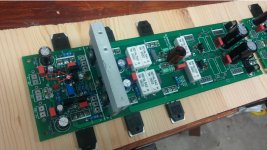
The transistor marked by the red arrow is the VBE for the outputs. It needs to be mounted on the main heatsink to sense temperature. Also the LED next to it is for the FET version. That needs to be a jumper for the BJT version.
Attachments
You shouldn't have the LED in above Q104. It should be jumpered out. You may need bigger drivers for 3 output pairs too. I thin TO220 is only good for 2 pairs of outputs. I posted a schematic with a little clearer explanation of parts needed for different versions here. http://www.diyaudio.com/forums/solid-state/260268-slewmaster-builds-109.html#post4422418
I believe that Pete said the HK amp he fashioned the Slewnaster OPS after used TO-220 drivers so they are likely OK.
Could be. I remember larger drivers being recommended for the three pair version of the first layout though.
LED is shorted from down side....OK, I will place this trans on main heatsink... I think this Toshibas can drive 3 outputs pairs... we will see 🙂)
I think there are two different builds going on concurrently, maybe causing some confusion.
Quan stated he is going MOSFET but isn't getting the bias generator to come up properly.
Maxwell007 appears to be doing a BJT build, but has a couple details to sort as per still4given's observations.
Quan stated he is going MOSFET but isn't getting the bias generator to come up properly.
Maxwell007 appears to be doing a BJT build, but has a couple details to sort as per still4given's observations.
Hi Jason, i am building the MOSFET version as per schematic and omitting the parts as build guide. The mocked resistors for IPS input sections are 10k and i am using 45VDC supply.
Quan
Quan
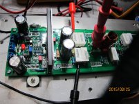
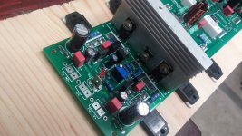
maybe it doesn't look like, but i am building BJT version with NJW.. 😀
Attachments
Last edited:
Quan,
G2 and G1 need a connection?
I have not tested OPS without IPS hooked up.
Hi Evan, i connected G2 and G1 under the board to keep it tidy. I measured 40V across the 10K mocked ips resistor under voltage mode but if i tried to measure the current across the mocked resistor then it read 20mA!!! with current mode and the bias led light up?. I am not sure what is going on. I have double check all values and transistors and all seem to be correct.
Quan
Your simulated bias current is about 4mA, try using a lower value set of resistors like 8K2 or 7K5 in place of the 10K to increase the mock IPS current a little. You likely just don't have enough current flow to get the bias circuit to turn on.
When you put an ammeter across (in parallel) the resistor you short it out and the current goes way up because now there is only one resistor in the mock IPS circuit. The meter, when in current or ammeter mode, must be in series with what you are measuring. With a known resistance you only need the voltage across the resistor and ohms law to know the current 😉.
When you put an ammeter across (in parallel) the resistor you short it out and the current goes way up because now there is only one resistor in the mock IPS circuit. The meter, when in current or ammeter mode, must be in series with what you are measuring. With a known resistance you only need the voltage across the resistor and ohms law to know the current 😉.
Your simulated bias current is about 4mA, try using a lower value set of resistors like 8K2 or 7K5 in place of the 10K to increase the mock IPS current a little. You likely just don't have enough current flow to get the bias circuit to turn on.
When you put an ammeter across (in parallel) the resistor you short it out and the current goes way up because now there is only one resistor in the mock IPS circuit. The meter, when in current or ammeter mode, must be in series with what you are measuring. With a known resistance you only need the voltage across the resistor and ohms law to know the current 😉.
Thank you Jason, that make sense. I will try a lower mocked ips resistor then report back.
Quan
Hi
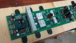
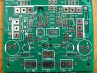
I need some help with the capacitors on the latest PC boards (with the 5pair power transistors)
I got some transformers which will give me +/- 80 to 81V after rectification
I want to place an order at Parts Connexion but for that I need to know the next capacitors value and voltage or
C105 & C102 22uF V???
C103 & 106 220uF V rating ??
C107 1uF 50V to my 80VDC supply is OK?
Again I build BJT version with 5 pair power transistors 80-81VDC power supply (with out any load) I do not want to buy 100V caps everywhere if is no need for, also the 100V cap size can be a issue if I need only 63V or so..
Please let me know
Thank you guys 🙂
Attachments
Last edited:
- Home
- Amplifiers
- Solid State
- SlewMaster Builds